background image

– 7 –

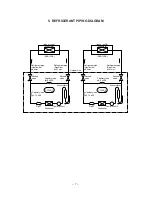
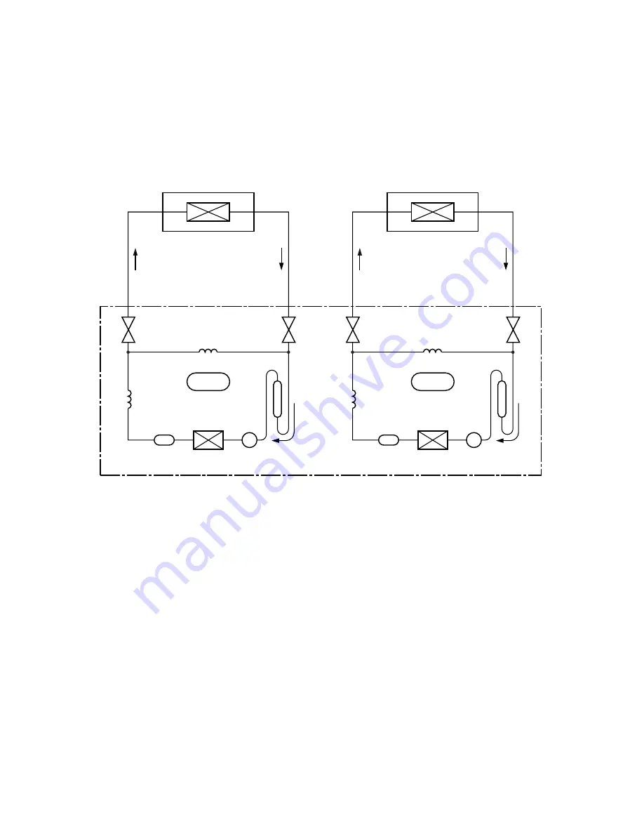
5.  REFRIGERANT PIPING DIAGRAM

Evaporator

(Indoor unit A)

(RAS-13SK)

CYCLE 1

Condenser

Dryer

Compressor 1

Accumulator

Refrigerant pipe
(Liquld side)

φ

6,4mm

Packed 
valve

Capillary tube

φ

1,7 x 600

Packed 
valve

Refrigerant pipe
(Gas side)

φ

12,7mm

Outdoor Unit

Capillary tube

φ

0,6 x 600

Evaporator

(Indoor unit B)

(RAS-13SK)

CYCLE 2

Condenser

Dryer

Compressor 2

Accumulator

Refrigerant pipe
(Liquld side)

φ

6,4mm

Packed 
valve

Capillary tube

φ

1,7 x 600

Packed 
valve

Refrigerant pipe
(Gas side)

φ

12,7mm

Capillary tube

φ

0,6 x 600

Summary of Contents for RAV-M242A

Page 1: ...CONDITIONER FILE NO A10 9801 PRINTED IN JAPAN Mar 1998 ToMo SUPPLEMENT Unit A Unit B RAS 13SK E or RAS 13SKX RAV M242A E or RAV M242A RAV M242A E SPLIT WALL TYPE Combination with RAS 13SK E RAV M242A Combination with RAS 13SKX ...

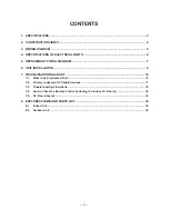
Page 2: ...AGRAM 7 6 UNIT INSTALLATION 9 7 TROUBLESHOOTING CHART 10 7 1 What to be Prechecked First 10 7 2 Primary Judgement ofTrouble Sources 11 7 3 Troubleshooting Flowcharts 15 7 4 How to Check the Remote Control Including the Indoor P C Board 20 7 5 P C Board Layout 23 8 EXPLODED VIEWS AND PARTS LIST 25 8 1 Indoor Unit 25 8 2 Outdoor Unit 26 ...

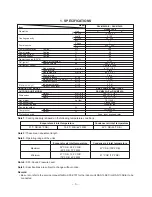
Page 3: ...ngth One way 2 m ft Minimum length m ft Maximum height Indoor unit higher m ft Outdoor unit higher m ft INDOOR UNIT MODEL OUTDOOR UNIT MODEL Height mm ft in Dimensions Width mm ft in Depth mm ft in Net weight kg Ibs Condenser type Condenser fan type Fan motor output W Compressor Model Output W Protective device Condenser air inlet temperature 35 C DB 95 F DB Evaporator air inlet temperature 27 C D...

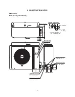
Page 4: ...oint Liquid side 2 ø6 4 34 86 Power supply cord hole ø19 knockout hole Inter unit wiring cord hole ø28 knockout hole 65 60 107 33 790 Air outlet Electric parts box Carrying handle Both side Electric parts cover 100 Outlet Space for wiring and piping 100 Space required for service Space for service When installing the inlet is to be faced the wall side 300 500 Anchor bolt hole 4 12x18 long hole ...

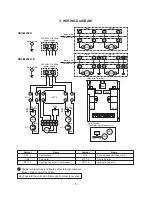
Page 5: ...etic contacto 11 L N 12 CM1 RCo1 RCo WHI BLK BLK RED RED 51C1 52C1 52C2 220 240V 1Ph 50Hz power supply Outdoor Unit Earth screw Indoor Unit 13 14 15 16 6 11 12 CM2 RCo2 WHI BLK BLK RED RED 51C2 13 14 A B 5 4 3 2 1 6 5 4 3 2 1 FMo 1 2 1 52C1 A B 52C2 Unit A Unit B 2 1 2 1 2 A B 1 2 1 52C1 A B 52C2 Unit A Unit B 2 1 2 1 2 Electrical Parts Box Parts Position Fan Motor Compressor Coil RCo 52C2 RCc2 RC...

Page 6: ...0X2 4L Output 1 1 kW 2 pole 1 φ 220 240 V 50 Hz Winding resistance Main coil 2 2 Ω Aux coil 3 8 Ω Fan motor STF 200 63B Output 63 W 6 pole 1 φ 220 240 V 50 Hz Magnetic contactor VC20FA AC 240 V Capacitor MT 40MP356W For compressor 1 2 AC 400 V 35 µF EAG45M355UF1 For fan motor AC 450 V 3 5 µF ...

Page 7: ...acked valve Capillary tube φ1 7 x 600 Packed valve Refrigerant pipe Gas side φ12 7mm Outdoor Unit Capillary tube φ0 6 x 600 Evaporator Indoor unit B RAS 13SK CYCLE 2 Condenser Dryer Compressor 2 Accumulator Refrigerant pipe Liquld side φ6 4mm Packed valve Capillary tube φ1 7 x 600 Packed valve Refrigerant pipe Gas side φ12 7mm Capillary tube φ0 6 x 600 ...

Page 8: ...hosphate deoxi dized copper seamless pipes for air conditioners Model RAS 13SK E or RAS 13SKX Piping size mm Larger Smaller 12 7 6 4 5 1 3 Air Purging Subject the refrigerant tube of outdoor and indoor units to air purge with a vacuum pump Do not carry out this air purge by using the refrig erant filled in the outdoor unit To handle valves a 5mm hexagon wrench is needed 5 1 4 Refrigerant Pipe Conn...

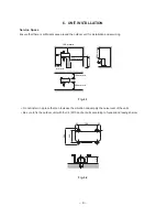
Page 9: ...icing Fig 6 1 Do not install in a place that can increase the vibration and amplify the noise level of the units Be sure to fix the outdoor unit with four 4 M10 anchor bolts according to foundation drawings below 45 45 790 340 15 364 100 or more 500 or more 500 or more 300 or more 100 or more 500 or more 100 or more Fig 6 2 ...

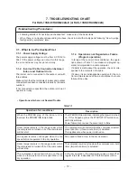
Page 10: ... thermostat control is operated in the dry operation 7 TROUBLESHOOTING CHART For RAS 13SK E RAV M242A E or RAS 13SKX RAV M242A Troubleshooting Procedures Following details of What to be prechecked first make sure of the basic items When there is no trouble corresponding to above check in detail the faulty parts following How to judge faulty parts by symptoms later 7 1 What to be Prechecked First 7...

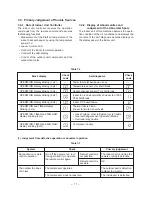
Page 11: ...machine observes the opera tion condition of the air conditioner and displays the contents of the self diagnosis as block displays on the display panel of the indoor unit System No reaction on remote control operation The outdoor fan does not rotate Check Turn off the power once turn it on again and try to operate the remote control again The compressor operates The compressor does not operate Pri...

Page 12: ...temperature is displayed on the display and other display is turned off ACL CLOCK Rear bottom of remote control ACL CLOCK All clear button Switch for selecting service mode Rear bottom cover 2 Selecting ordinary mode Push the all clear button ACL on the rear bot tom of the wireless remote control by a tip of pencil for more than 3 seconds Make sure the operation mode display wind volume display cl...

Page 13: ...is by the check codes is con ducted under the block displays of item b e Indication after operation 1 is added to data before operation Example 1 is subtracted from data before operation Example 10 is subtracted from data before operation Example Data before operation is directly transferred Example Operating key ON OFF TEMP Up TEMP Down AUTO LOUVER SET LOUVER Table 7 4 d Operate the TEMP key and ...

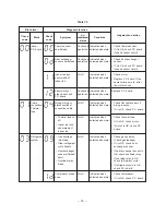
Page 14: ...etected abnormal Indicated when detected abnormal Indicated when detected abnormal Indicated when detected abnormal Indicated when detected abnormal Block Indoor P C board Cable connection Thermal fuse Refrigerant system Judgment and action Check thermo sensor If it is OK check P C board Around sensor circuit Check heat exchanger sensor If it is OK check P C board Around sensor circuit Check motor...

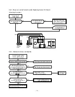
Page 15: ...t off the power supply once and turn it on again after dis connecting the motor connector CN10 Is the secondary voltage of SW transformer measured DC35V DC12V and DC7V Motor is defective Is the secondary voltage of SW trans former T01 measured DC35V DC12V and DC7V YES SW transformer T01 or IC IC01 for power supply is defective Parts R21 R109 SG01 C15 C01 DB01 C02 IC01 T01 are defective Does the po...

Page 16: ...Does the OPERATION lamp blink Does the power turn on by pushing the START STOP button of the remote control Is cable connection between indoor and outdoor units correct Check items as following procedure in 7 3 4 7 3 5 7 3 6 Replace the P C board See Power can not be turned on Relays RY01 RY02 or IC31 or IC30 is failure Correct cabling between indoor and outdoor units NO NO NO NO YES YES YES YES S...

Page 17: ...or Is the capacitor for compressor normal Is the overload relay normal Does the compressor start Compressor starts but it stops after a while Cables between indoor and outdoor units are defective Re wire or replace the defective cords Compressor is defective Capacitor is defective Overload relay is defective Compressor is defective Correct cabling between indoor and outdoor units NO NO NO NO NO NO...

Page 18: ...e capacitor for compressor normal Outdoor fan motor is defective Cables between indoor and outdoor units are defective Outdoor fan motor is defective Correct cabling between indoor and outdoor units NO NO NO NO YES YES YES YES Are all the cords for outdoor fan motor normal Correct the wire or replace the defective cords Capacitor for outdoor fan motor is defective See Power can not be turned on Re...

Page 19: ... fan Turn on the power supply Is the rotation signal DC 5V 0V output between 4 blue lead wire and 2 black lead wire of the motor connector CN10 when rotating the cross flow fan by hand in no operating status two pulses one turn Replace the control P C board Shut off the power supply and turn it on after disconnecting the motor connector CN10 from the P C board Is the voltage of DC35V measured betw...

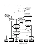
Page 20: ...d nearer to the infrared signal receiver of the air conditioner Battery life Can any signal tone be heard in a transistor radio when transmitting within 5cm distance from the radio Does the transmission indicator light Is there any beep and operation Short circuit the metal terminal at the side of the battery compartment all clear terminal with a pencil wait about 10 seconds P C Board is failure R...

Page 21: ... C board hold the whole housing Do not pull at the lead wire 2 Inspection procedures 1 When a P C board is judged to be defective check for disconnection burning or discolora tion of the copper foil pattern or this P C board 2 The P C board consists of the following two parts a Main P C board part Power relay indoor fan motor drive circuit and control circuit C P U and peripheral cir cuits buzzer ...

Page 22: ... 11 of IC31 and GND 2 Between No 1 and 2 of connecting cable terminal block 220 230 240V AC 1 All indicators light for 3 sec 2 Indicators do not indicate normally after approximate 3 sec 1 Compressor does not operate 2 OPERATION lamp blinks 1 Compressor does not operate 2 OPERATION lamp blinks 1 The voltage of DC 35V is not measured between the red and black of the motor terminals 2 Motor does not...

Page 23: ... 23 7 5 P C Board Layout Top View Bottom View ...

Page 24: ... 7 Approximate value of the sensor thermistor resistance TA TC kΩ 7 5 1 How to Reduce the Operation Time of the Anti restart Timer Drill 2 holes on the rear of the wireless remote control unit Attach the diode 1S1555 or equivalent to the rivet inside the unit Push the START STOP button to start operation with the diode attached Fig 7 2 ...

Page 25: ...2 43T69004 Sensor Heat Exchanger 10kΩ 25 C 403 43T69005 Sensor Thermostat 10kΩ 25 C 404 43T60004 Fuse Temperature 77 C Location Part Description No No 405 43T69007 P C Board WRS LED MCC 635 406 43T69017 P C Board MCC 713 407 43T61001 Base E Parts ABS Black UL94 5V 408 43T62006 Base Shield SGCC Z08 LUB Location Part Description No No ...

Page 26: ...00 63B 12 43191494 Guard Fan 13 43046151 Valve 2 way 19 43046232 Packed Valve 12 7 Location Part No Description No 21 43046228 Packed Valve 6 35 22 43145103 Dryer 23 43119390 Hanger 24 43146443 Solenoid Coil 25 43047492 Capillary Tube 1 7 Dia 26 43047491 Capillary Tube 1 5 Dia 29 43049625 Cushion Rubber 30 43069988 Holder OL Relay 12 01 10 22 02 03 24 13 25 29 21 19 30 03 23 26 ...

Page 27: ...No 05 43154139 Switch Magnetic 06 43160479 Terminal Block 2P 07 43160466 Terminal Block 4P RAV M242A 07 43160480 Terminal Block 6P RAV M242A E Location Part No Description No 08 43055354 Capacitor Plastic Film 35MFD 400V 14 43054380 Relay Overload 18 43155146 Capacitor Electrolytic 32 43150220 Bimetal Thermostat ...

Page 28: ......

Reviews: