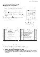
8-1-4. Cabling and Setting of Remote Controller Control
(Setup method)
One or multiple indoor units are controlled by two
remote controllers.
(Max. 2 remote controllers are connectable.)
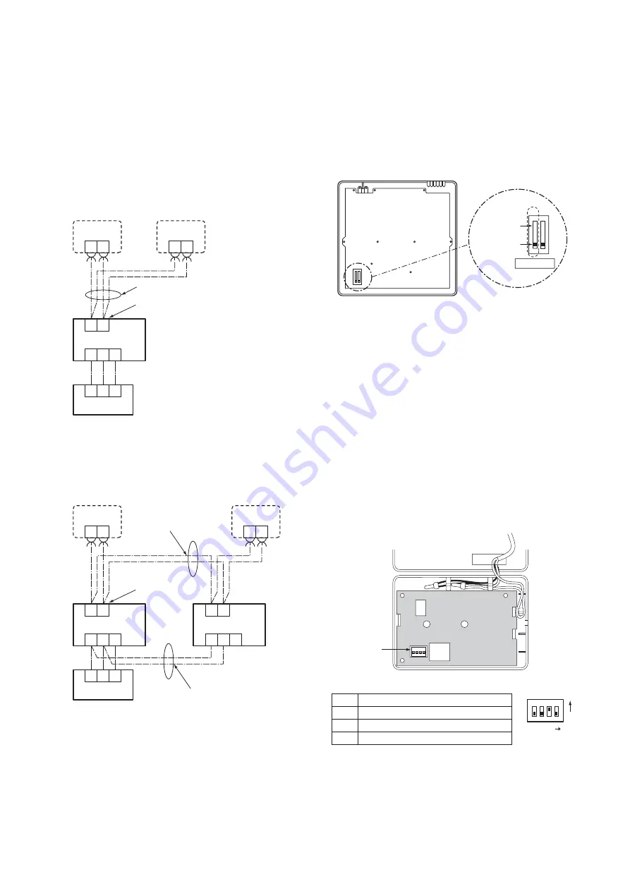
2-remote controller control
(Controlled by 2 remote controllers)
This control is to operate 1 or multiple indoor units
are controlled by 2 remote controllers.
(Max. 2 remote controllers are connectable.)
• When connected 2 remote controllers
operate an idoor unit
<Wired remote controller>
How to set wired remote controller
as sub remote controller
Change DIP switch inside of the rear side of the
remote controller switch from remote controller
master to sub. (In case of RBC-AMT32E)
• When connected 2 remote controllers
operate the twin
Terminal block for
remote controller cables
Remote controller
cables (Procured locally)
Indoor unit
Outdoor unit
Remote controller
switch (Sub)
Remote controller
switch (Master)
Sold
separately
2
1
3
2
1
3
B
A
B
A
B
A
Sold
separately
Terminal block for
remote controller cables
Indoor unit 1
Outdoor unit
Remote controller
switch (Sub)
Remote controller
switch (Master)
Sold
separately
2
1
3
2
1
3
B
A
B
A
B
A
Indoor unit 2
2
1
3
B
A
Sold
separately
Remote controller
inter-unit wire
(Procured locally)
Inter-unit wiring
between indoor units
(Procured locally)
1 2
1 2
1 2
Remote controller (Inside of the rear side)
Sub remote
controller
Master remote
controller
DIP switch
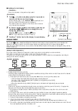
<Wireless remote controller>
Remote controller address (A-B selection)
setting
• When two or more signal receiving units are
installed in a room, a unique address can be set for
each signal receiving unit to prevent interference.
• Address (A-B selection) must be changed on both
signal receiving unit and wireless remote controller.
• For the details of address change (A-B selection) on
wireless remote controller, refer to the owner’s
manual.
Turn off the indoor unit power supply. Turn on the bit 3
of DIP switch SW30 on the signal receiving unit P.C.
board.
The setting change is shown below.
DIP-Switch [SW30]
4
ON=Follower
OFF=Header
3
ON=B
OFF=A
2
Not used
1
Not used
SW30
SW30
Bit3 : OFF ON
ON
1
ON
2
3
4
FILE NO. SVM-18039
- 68 -
Summary of Contents for RAV-RM1101BTP Series
Page 18: ...RM56 type RM80 type RM110 RM140 type FILE NO SVM 18039 18 ...
Page 19: ...3 WIRING DIAGRAM FILE NO SVM 18039 19 ...
Page 34: ...5 3 Indoor Print Circuit Board MCC 1631 FILE NO SVM 18039 34 ...
Page 89: ...11 EXPLODED VIEWS AND PARTS LIST 11 1 RAV RM561BTP E RAV RM561BTP TR FILE NO SVM 18039 89 ...
Page 91: ...11 2 RAV RM801BTP E RAV RM801BTP TR FILE NO SVM 18039 91 ...
Page 94: ...11 6 RAV RM1101BTP E RAV RM1101BTP TR RAV RM1401BTP E RAV RM1401BTP TR FILE NO SVM 18039 94 ...


