background image

– 24 –

11

Troubleshooting

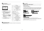
Confirmation and check

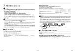
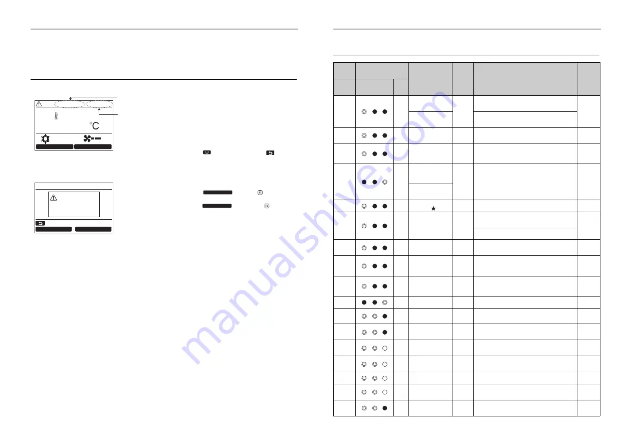
When a trouble has occurred in the air 
conditioner, the check code and the unit number 
of the indoor unit appear on the display of the 
remote controller.

* The check code appears only while the unit is 

running.

Push the [

 MONITOR] button or [


CANCEL] button to display the check information 
screen.

While the check information screen appears:
Push the “


Contact” [


F1] button to 

display the contact number for service.
Push the “


Information” [


F2] button 

to display the model name and serial number of 
the unit.

Cool

24

Mode

Fan Speed

Code : P10     Unit : 2–2

Check code

Unit number of the 

malfunctioning 

indoor unit

Check

Contact

Information

Return

Check

Code:P10

Unit:2–2

Contact

Information

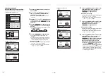
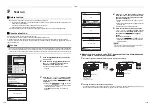
Check codes and parts to be checked

Remote 

controller 

display

Wireless remote controller

Sensor block display of 

receiving unit

Main defective parts

Judging 

device

Parts to be checked / trouble description

Air 

conditioner 

status

Indication

Operation Timer    

Ready

 GR GR OR

Flashing

E01

No header remote 

controller

Remote 

controller

Incorrect remote controller setting --- The header 

remote controller has not been set (including two 

remote controllers). 

*

Remote controller 

communication 

trouble

No signal can be received from the indoor unit.

E02

Remote controller 

transmission trouble

Remote 

controller

Indoor / outdoor connecting wires, indoor P.C. board, 

remote controller 


--- No signal can be sent to the indoor unit.

*

E03

Indoor unit-remote 

controller regular 

communication 

trouble 

Indoor

Remote controller, network adapter, indoor P.C. 

board --- No data is received from the remote 

controller or network adapter.

Auto-

reset

E04

Indoor unit-outdoor 

unit serial 

communication 

trouble

Indoor

Indoor / outdoor connecting wires, indoor P.C. board, 

outdoor P.C. board --- Serial communication trouble 

between indoor unit and outdoor unit

Auto-

reset

IPDU-CDB 

communication 

trouble

E08

Duplicated indoor 

addresses 

Indoor

Indoor address setting trouble --- The same address 

as the self-address was detected.

Auto-

reset

E09

Duplicated header 

remote controllers

Remote 

controller

Remote controller address setting trouble --- Two 

remote controllers are set as header in the double-

remote controller control.

*

 (* The header indoor unit stops raising alarm and 

follower indoor units continue to operate.) 

E10

CPU-CPU 

communication 

trouble

Indoor

Indoor P.C. board --- Communication trouble between 

main MCU and motor microcomputer MCU

Auto-

reset

E11

Communication 

trouble between 

Application control kit 

and Indoor unit

Indoor

Communication trouble between Application control 

kit and Indoor unit

Entire 

stop

E18

Header unit follower 

unit regular 

communication 

trouble

Indoor

Indoor P.C. board --- Regular communication is not 

possible between header and follower indoor units or 

between twin header (main) and follower (sub) units.

Auto-

reset

E31

IPDU communication 

trouble

Outdoor

Communication trouble between IPDU and CDB

Entire 

stop

F01

ALT

Indoor unit heat 

exchanger sensor 

(TCJ) trouble

Indoor

Heat exchanger sensor (TCJ), indoor P.C. board --- 

Open-circuit or short-circuit of the heat exchanger 

sensor (TCJ) was detected.

Auto-

reset

F02

ALT

Indoor unit heat 

exchanger sensor 

(TC) trouble

Indoor

Heat exchanger sensor (TC), indoor P.C. board --- 

Open-circuit or short-circuit of the heat exchanger 

sensor (TC) was detected.

Auto-

reset

F04

ALT

Outdoor unit 

discharge temp. 

sensor (TD) trouble

Outdoor

Outdoor temp. sensor (TD), outdoor P.C. board --- 

Open-circuit or short-circuit of the discharge temp. 

sensor was detected.

Entire 

stop

F06

ALT

Outdoor unit temp. 

sensor (TE / TS) 

trouble

Outdoor

Outdoor temp. sensors (TE / TS), outdoor P.C. board 

--- Open-circuit or short-circuit of the heat exchanger 

temp. sensor was detected.

Entire 

stop

F07

ALT

TL sensor trouble

Outdoor

TL sensor may be displaced, disconnected or short-

circuited.

Entire 

stop

F08

ALT

Outdoor unit outside 

air temp. sensor 

trouble

Outdoor

Outdoor temp. sensor (TO), outdoor P.C. board --- 

Open-circuit or short-circuit of the outdoor air temp. 

sensor was detected.

Operation 

continued

F10

ALT

Indoor unit room 

temp. sensor (TA) 

trouble

Indoor

Room temp. sensor (TA), indoor P.C. board --- Open-

circuit or short-circuit of the room temp. sensor (TA) 

was detected.

Auto-

reset

47-EN

48-EN

Summary of Contents for RAV-RM1101FT-EN

Page 1: ...RM801FT ES RAV RM1101FT ES RAV RM1401FT ES RAV RM1601FT ES AIR CONDITIONER SPLIT TYPE Installation Manual For commercial use R32 or R410A For details of setting up remote controller built in this unit refer to the separate Owner s Manual and Installation Manual of remote controller This Installation Manual describes only major items English ...

Page 2: ...o is allowed to do the refrigerant handling and piping work involved in installation relocation and removal has the qualifications pertaining to this refrigerant handling and piping work as stipulated by the local laws and regulations and he or she is a person who has been trained in matters relating to refrigerant handling and piping work on the air conditioners made by Toshiba Carrier Corporatio...

Page 3: ...w meanings of indications and be sure to follow the description 1 Serious bodily harm indicates loss of eyesight injury burns electric shock bone fracture poisoning and other injuries which leave aftereffect and require hospitalization or long term treatment as an outpatient 2 Slight injury indicates injury burns electric shock and other injuries which do not require hospitalization or long term t...

Page 4: ...on cycle which may result in a failure or explosion of the product or an injury to your body Before opening the intake grille of the indoor unit or service panel of the outdoor unit set the circuit breaker to the OFF position Failure to set the circuit breaker to the OFF position may result in electric shocks through contact with the interior parts Only a qualified installer 1 or qualified service...

Page 5: ...rn refrigerant cycle parts Do not use means to accelerate the defrosting process or to clean other than those recommended by the manufacturer Be aware that refrigerants may not contain an odor Pipe work shall be protected from physical damage Compliance with national gas regulations shall be observed If refrigerant leak detection sensor detects R32 refrigerant leak a fan on indoor unit automatical...

Page 6: ...ght test The charge hose must be connected in such a way that it is not slack Electrical wiring Only a qualified installer 1 or qualified service person 1 is allowed to carry out the electrical work of the air conditioner Under no circumstances must this work be done by an unqualified individual since failure to carry out the work properly may result in electric shocks and or electrical leaks To c...

Page 7: ... the event that trouble has occurred in the air conditioner After the installation work follow the Owner s Manual to explain to the customer how to use and maintain the unit Relocation Only a qualified installer 1 or qualified service person 1 is allowed to relocate the air conditioner It is dangerous for the air conditioner to be relocated by an unqualified individual since a fire electric shocks...

Page 8: ...combustion appliances will be sucked into the unit Doing so may cause the heat exchanger its aluminum fins and copper pipes and other parts to become corroded Locations with atmospheres with mist of cutting oil or other types of machine oil Doing so may cause the heat exchanger to become corroded mists caused by the blockage of the heat exchanger to be generated the plastic parts to be damaged the...

Page 9: ...sulator to the side face and the rear side of the indoor unit To open the intake grille Direction of vertical louver The intake grille is fixed by the screws for safety reasons Use a screwdriver to unfasten the screws of the intake grille two places to open the intake grille The screws are designed to stay on the intake grille The direction of the auto turn louver Vertical louver may change during...

Page 10: ...packed by necessity use buffering cloth or other material not to damage the unit Carry the package by four or more persons and do not bundle it with plastic band at positions other than specified Be sure to take measures to prevent falling at the wall surface and the floor and fix it surely considering prevention of accident of falling because this unit is formed into a thin type If it is not fixe...

Page 11: ...and then fix the indoor unit at total four positions two positions for right and left each Unit mm Indoor unit fixing figure Wooden wall Screw bolts Concrete wall Anchor bolts 0 mm 50 mm 1770 mm Fixing height of screw bolt or anchor bolt 1730 mm Fixing height of screw bolt or anchor bolt Clearance Height of head of fixing bolt Model A B RM56 to RM80 type 88 30 to 80 RM110 to RM160 type 258 40 to 9...

Page 12: ...erial putty to the clearance at penetration part Pipe material size and heat insulator The following materials for piping work and insulating process are procured locally Pipe material Hard vinyl chloride pipe PVC pipe VP20 Internal diameter 20 mm external diameter 26 mm Heat insulator Foamed polyethylene foam thickness 6 mm or more Connecting drain pipe REQUIREMENT Using adhesive agent for vinyl ...

Page 13: ...nerated CAUTION IMPORTANT 4 POINTS FOR PIPING WORK 1 Reusable mechanical connectors and flared joints are not allowed indoors When mechanical connectors are reused indoors sealing parts shall be renewed When flared joints are reused indoors the flare part shall be refabricated 2 Tight connection between pipes and unit 3 Evacuate the air in the connecting pipes by using VACUUM PUMP 4 Check the gas ...

Page 14: ...It is necessary to fix the compressor and refrigeration cycle malfunction Open the valve fully CAUTION A brazed welded or mechanical connection shall be made before opening the valves to permit refrigerant to flow between the refrigerating system parts Open the valve of the outdoor unit fully A 4 mm hexagonal wrench is required for opening the valve For details refer to the Installation Manual att...

Page 15: ...ire wire size Including earth line Indoor unit power supply 1 50 Hz 220 240 V Indoor Outdoor connecting wires 4 1 5 mm2 or more H07 RN F or 60245 IEC 66 Up to 70 m A B Remote controller wiring For this indoor unit a remote controller RBC AMS55E is built into the unit L length of remote controller wiring is 2 5 m CAUTION The remote controller wire and Indoor Outdoor connecting wires cannot be paral...

Page 16: ... Remote controller Remote controller Remote controller Master Sub Indoor side Indoor side Remove connector Remote controller inter unit wiring Remote controller inter unit wiring Wire connection REQUIREMENT Connect the wires matching the terminal numbers Incorrect connection causes a trouble Pass the wires through the bushing of wiring holes of the indoor unit The low voltage circuit is provided f...

Page 17: ... settings The settings cannot be changed using the wireless remote controller simplified wired remote controller or remote controller less system for central remote controller only Basic procedure for changing settings Change the settings while the air conditioner is not working Stop the air conditioner before making settings CAUTION Set only the Code DN ˮ shown in the following table Do not set a...

Page 18: ...tting According to the installation condition the filter sign term Notification of filter cleaning can be changed Follow to the basic procedure 1 2 3 4 5 For the Code DN in Procedure 3 specify 0001 For the Data in Procedure 3 select the Data of filter sign term from the following table To secure better effect of heating When it is difficult to obtain satisfactory heating due to installation place ...

Page 19: ...perating current x1 10 6D Outdoor heat exchange coil temperature TL F1 Compressor cumulative operating hours x100 h Group control Simultaneous twin triple or double twin system A combination with an outdoor unit allows simultaneous ON OFF operation of the indoor units The following system patterns are available Two indoor units for the twin system Three indoor units for the triple system Four indo...

Page 20: ...unit Outdoor unit Outdoor unit NOTE In some cases it is necessary to change the address manually after setup of the automatic address according to the system configuration of the group control The following mentioned system configuration is a case of complex systems in which systems of the simultaneous twin and simultaneous triple unit is controlled as a group by a remote controller Example Group ...

Page 21: ...g Code DN Data 3 3 Return 0002 0012 Fix Set Unit 1 1 1 2 3 3 Set Address is displayed here Address is displayed here 6 Push the MENU button to set the other Code DN and Data After Continue is displayed on the screen push the Yes F1 button Indoor address change Change Code DN from 0010 to 0013 with the button Change Data from 0003 to 0002 with the button 7 Push the MENU button to set the other Code...

Page 22: ...reen returns to the Field setting menu screen Push CANCEL twice the screen 2 appears 1 Test mode 2 Register service info 3 Alarm history 4 Monitor function 5 Setting louver position Field setting menu 1 2 Return Set 1 Test mode 2 Register service info 3 Alarm history 4 Monitor function 5 Setting louver position Field setting menu 1 2 Return Set Set Yes Return Test mode start No Yes Test mode Measu...

Page 23: ...itioner when filter sign appears on the detailed display Push one of the operation buttons to erase the message or wait for more than 5 seconds until the message disappears Cool 24 Room A 12 00 Mode Fan Speed Filter sign Filter check Room A 12 00 Mode Fan Speed 1 Push the ON OFF button to stop the operation then turn off the circuit breaker 2 Use a screwdriver to unfasten the screws of the intake ...

Page 24: ...if there are any waggles damages or adhesive dust Filter Go to installed location and check if there are any stains or breaks on the filter Drain pan Access from inspection opening and remove the access panel Check if there is any clogging or drain water is polluted Refrigerant leak detection sensor Open the intake grille and E BOX and check if there are any troubles on sensor s appearance or its ...

Page 25: ...as detected Auto reset E09 Duplicated header remote controllers Remote controller Remote controller address setting trouble Two remote controllers are set as header in the double remote controller control The header indoor unit stops raising alarm and follower indoor units continue to operate E10 CPU CPU communication trouble Indoor Indoor P C board Communication trouble between main MCU and motor...

Page 26: ...e to incorrect external input into CN80 Entire stop L31 SIM Phase sequence trouble etc Outdoor Power supply phase sequence outdoor unit P C board Abnormal phase sequence of the 3 phase power supply Operation continued thermos tat OFF Remote controller display Wireless remote controller Sensor block display of receiving unit Main defective parts Judging device Parts to be checked trouble descriptio...

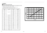
Page 27: ...1 50 5 70 14 36 1 60 5 80 14 61 1 70 5 90 14 86 1 80 6 00 15 11 1 84 4 64 6 10 15 36 1 90 4 79 6 20 15 62 2 00 5 04 6 30 15 87 2 10 5 29 6 40 16 12 2 20 5 54 6 50 16 37 2 30 5 80 6 60 16 62 2 40 6 05 6 70 16 87 2 50 6 30 6 80 17 13 2 60 6 55 6 90 17 38 2 70 6 80 7 00 17 63 2 80 7 05 7 10 17 88 2 90 7 31 7 20 18 13 3 00 7 56 7 30 18 38 3 10 7 81 7 40 18 64 3 20 8 06 7 50 18 89 3 30 8 31 7 60 19 14 ...

Page 28: ...EB99832901 336 TADEHARA FUJI SHI SHIZUOKA KEN 416 8521 JAPAN Toshiba Carrier Corporation ...

Reviews: