background image

52

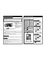
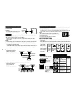
HOW TO  ADJUST  AIR  DIRECTION

• Never move the flap (Air direction up/down adjusting plate) which is operated on the remote

controller with hands except a case of cleaning of the flap.

• While the unit stops, the flap (Air direction up/down adjusting plate) directs downward auto-

matically.

• During preparation of heating, the flap (Air direction up/down adjusting plate) directs upward.

The swinging operation starts after heating preparation status has been cleared. However,
swinging is displayed on the AUTO flap display of the remote controller even if the heating
operation is being prepared.

How to set up the air direction

Every pushing 

 button during operation, the air direction changes.

How to start swinging

When pushing 

 button, set the direction of the flap (Air direction up/down adjusting plate) to

the lowest position, and then push 

 button again, the swinging is displayed and the air direction

automatically changes upward/downward.

How to stop swinging

Pushing 

 button once again during swinging of the flap stops the flap at the desired position.

Then, when pushing 

 button, the air direction can be set to position from the uppermost

position.
• In cooling or dry operation, the flap does not stop when the flap directs downward.

If doing so, the flap stops at the 3

rd

 position from the uppermost position.

In heating operation

Direct the flap (Air direction up/down adjusting plate) down-
ward, otherwise the hot air may not reach at the foot.

In cooling/dry operation

Direct the flap (Air direction up/down adjusting plate) upward,
otherwise dewdrops may adhere or drip down to near of the
discharge grille.

In air
blowing operation

In all
operation modes

Display when swinging stopped

Initial setup

Initial setup

Initial setup

Series of 
operation

Fan/Heat operation

Cool/Dry operation

SLIDE SWITCH

• Do not change setting of the slide switch because a malfunction occurs by other settings.
• Before usage, check the slide switch is set to the position as follows;

HOW TO  INSERT THE  BATTERIES

1. Holding the both sides of the cover and remove it by sliding downward.
2. Correctly insert 2 AAA alkali batteries ma and - polarities with indications.
3. Push RESET button with something tipped and attach the cover.

• Replace the batteries when the display section of the remote controller is difficult to be read,

or when the signal cannot be sent if you are not close to the sensor.
(The standard replacement time of the alkali batteries is approx. one year.)

• Use the same type of new batteries for replacing two batteries.
• In case when you do not the remote controller

for a long time, remove the batteries.

S K N

A H C

S K N

A H C

Removal of battery cover

Operation mode display 

of remote controller

Slide switch position

Swing

Slide switch position

Flashing position 

on remote controller

Corresponding model 

for change of flap

HIGH

MED.

RESET button

Cover

Summary of Contents for RAV-SM1101CT-E

Page 1: ...R410A FILE NO A03 015 SERVICE MANUAL OWNER S MANUAL INSTALLATION MANUAL UNDER CEILING TYPE INDOOR UNIT RAV SM561CT E RAV SM801CT E RAV SM1101CT E RAV SM1401CT E PRINTED IN JAPAN Feb 2004 ToMo ...

Page 2: ... involves dangerous work in high places so be sure to have a service person do it Do not attempt it yourself The cleaning diagram for the air filter is there for the service person and not for the customer CAUTION This manual indicates the indoor unit Under Ceiling type and it s accessory only About outdoor units subject refer as below SERVICE MANUAL RAV SM XXX AT E A03 008 RAV SP XXX AT E A03 014...

Page 3: ... E RAV SM801CT E RAV SM1101CT E RAV SM1401CT E OWNWE S MANUAL ACCESSORIES SOLD SEPARATELY 4 PRECAUTIONS FOR SAFETY 4 PARTS NAME 6 PARTS NAME OF REMOTE CONTROLLER 7 CORRECT USAGE 9 AUTOMATIC OPERATION Auto Changeover 10 ADJUSTMENT OF WIND DIRECTION 11 TIMER OPERATION 12 MAINTENANCE 14 AIR CONDITIONER OPERATIONS AND PERFORMANCE 15 RE INSTALLATION 16 TROUBLES AND CAUSES 16 INSTALLATION MANUAL Accesso...

Page 4: ...leaning diagram for the air filter is there for the service person and not for the customer Avoid cooling the room too strong or exposing the human body to cool breeze for a long time as it is bad for the health When you notice something abnormal with the air conditioner smells like some thing scorching poor cooling etc immediately turn off the main switch the circuit breaker from the mains to sto...

Page 5: ... room Poor ventilation causes oxygen shortage Do not place any combustion appliance in a place where it is directly exposed to the wind of air conditioner otherwise it may cause imperfect combustion When the air conditioner is used in a closed room be careful of sufficient ventilation of the room Poor ventilation causes oxygen shortage Do not touch any switches with wet finger otherwise you may ge...

Page 6: ... Air filter Removes dust or trash Provided on the suction port Discharge flap of discharge port Change the direction of the air to be discharged according to cool heat mode Suction air port The air in the room is sucked in from this port Outdoor unit The image of outdoor unit in the figure is in case Model RAV SM800AT E PARTS NAME Indoor unit ...

Page 7: ...the Timer SETIN button the display of the timer is selected in order of OFF OFF repeat OFF timer ON No display 6 Filter display If FILTER is displayed clean the air filter 7 TEST run display Displayed during a test run 8 Flap position display Displays flap position 9 SWING display Displayed during up down movement of the flap 10 Set up temperature display The selected set up temp is displayed 11 R...

Page 8: ...ts Erases FILTER display 6 UNIT and AUTO flap button UNIT No function 7 Operation lamp Lamp is lit during the operation Lamp is off when stopped Although it flashes when operating the protec tion device or abnormal time 8 button When the button is pushed the operation starts and it stops by pushing the button again When the operation has stopped the operation lamp and all the displays disappear 9 ...

Page 9: ...fficiently with VOLUME LOW opera tion select MED or HIGH operation 4 Determine the set up temperature by pushing the TEMP or TEMP button Stop Push button The operation lamp goes off and the operation stops CORRECT USAGE When you use the air conditioner for the first time or when you change the SET DATA value follow the proce dure below From the next time the operation displayed on the remote contr...

Page 10: ...select the Auto mode it is unnecessary to set the fan speed The FAN speed display will show AUTO and the fan speed will be automatically controlled After the heating operation has stopped FAN operation may continue for approx 30 seconds When the room temperature reaches the set temperature and the outdoor unit stops the supper low wind is discharged and the air volume decreases excessively During ...

Page 11: ...of up down wind direction downward If directing at upward hot air may not come to the foot In COOL DRY operation Direct the flap adjustment plate of up down wind direction upward If directing it downward the dew may from on the surface of the air discharge port and may drop down How to start swinging 1 Push set the flap adjustment plate of up down wind direction direction to the lowest position an...

Page 12: ...on the set time increases in the unit of 0 5 hr 30 minutes The maximum set time is 72 0 hr For every push of button the set time decreases in the unit of 0 5 hr 30 minutes The minimum set time is 0 5 hr 3 Push SET button SET DATA display disappears and display goes on When ON timer is activated time is displayed and after time of the timer has been up displays other than ON disappear Cancel of tim...

Page 13: ...ool or warm air in the room never open doors and windows more often than necessary Window curtains In cooling close the curtains to avoid direct sunlight In heating close the curtains to keep the heat in Get uniform circulation of room air Adjust the air flow direction for the even circulation of room air Control Gee chilly Clean please P l e a s e c l o s e Blows upward Blows downward Air flow ad...

Page 14: ...and maintenance of the indoor outdoor units are strongly recommended As a general rule if an indoor unit is operated for about 8 hours daily the indoor outdoor units will need to be cleaned at least once every 3 MONTH This cleaning and maintenance shall be carried out by a qualified person Failure to clean the indoor outdoor units regularly will result in poor performance icing water leaking and e...

Page 15: ...tion During the defrosting operation the defrosted water will be drained from the bottom plate of the outdoor unit Heating capacity In the heating operation the heat is absorbed from the outside and brought into the room This way of heating is called heat pump system When the outside temperature is too low it is recommended to use another heating apparatus in combination with the air conditioner A...

Page 16: ... the air conditioner in a place where it is usually exposed to strong wind such as in seaside area or on the roof or upper floor of a building Do not install the air conditioner in a place where sulfureous gas generated such as in a spa Do not install the air conditioner in a vessel or mobile crane Be careful with noise or vibrations Do not install the air conditioner in a place where noise by out...

Page 17: ...ts furniture clothing or furs come out Outdoor unit is frosted in heating operation Water drains from outdoor unit The outdoor unit is sometimes frosted in heating operation In that case the unit automatically performs defrosting for 2 to 10 minutes for increasing the heating efficiency In defrosting operation both the indoor and outdoor units stop air flow Hiss sound is heard when flow of the ref...

Page 18: ...ose 10t 200 200 For upper pipe hole of indoor unit 6t 130 160 For prevention of open of drain hose thermal insulator r Parts to be procured locally Connecting pipe Liquid side 6 4mm diam Nominal diam 1 4 thick 0 8mm RAV SM561CT E 9 52mm diam Nominal diam 3 8 thick 0 8mm RAV SM801CT E RAV SM1101CT E RAV SM1401CT E Connecting pipe Gas side 12 7mm diam Nominal diam 1 2 thick 0 8mm RAV SM561CT E 15 9m...

Page 19: ...ng designed for R410A and please care so that water or dust does not enter Moreover do not use the existing piping because there are problems with pressure resistance force and impurity in it CAUTION To Disconnect the Appliance from Main Power Supply This appliance must be connected to the main power supply by means of a switch with a contact separation of at least 3 mm The installation fuse 25A D...

Page 20: ...refrigerant gas has leaked during the installation work ventilate the room immediately If the leaked refrigerant gas comes in contact with fire noxious gas may generate After the installation work confirm that refrigerant gas does not leak If refrigerant gas leaks into the room and flows near a fire source such as a cooking range noxious gas might generate Electrical work must be performed by a qu...

Page 21: ...e unit can be installed horizontally Place where a sufficient servicing space can be ensured for safety maintenance and check Place where drained water will not cause any problem Avoid installing in the following places Place exposed to air with high salt content seaside area or place exposed to large quantities of sulfide gas hot spring Should the unit be used in these places special protective m...

Page 22: ...protector Remove the protectors 2 pcs of the fan RAV SM801CT only Suction grille Pull out suction grille while pushing hook Suction grille fixing knob Hinge S l i d e Slide forward Side panel Level flap Protector Setup data 0000 0001 Standard At shipment High ceiling 1 3 5m or less 4 0m or less According to the conditions of installation setup time of turning on of filter sign notification of filt...

Page 23: ...attern Upper pipe draw out port Knockout hole Power supply cable take in port Knockout Remote controller cable take in port Knockout hole Left drain size B Hanging position A Refrigerant pipe Liquid side ØC Refrigerant pipe Gas side ØD Drain pipe connecting port Drain port VP20 Inner dia Ø26 hose attached Pipe draw out port Knockout hole 200 Liquid pipe 216 Gas pipe Power supply cable take in port...

Page 24: ...pipe from right side Cut off the groove section with a metal saw or plastic cutter etc In case of taking pipe from left side Taking pipe from left side is applied only to the drain pipe The refrigerant pipe cannot be taken out from the left side Cut off the groove section with a metal saw or plastic cutter etc In case of taking pipe from upper side Taking pipe from upper side is applied only to th...

Page 25: ... material Holding down of main unit 1 Attach washer and nuts to the hanging bolt 2 Hang the unit to the hanging bolt as shown the figure below 3 As shown in the figure below fix the ceiling material securely with the double nuts REQUIREMENT The ceiling surface may not be horizontal Be sure to confirm that width and depth directions are level Installation of remote controller Sold separately For in...

Page 26: ...ating pipe Adhesive inhibited Use the attached flexible hose and hose band for connecting the drain hose to the clear drain socket If applying the adhesive socket will be damaged and cause water leakage Drain up When not securing down slope on the drain pipe use a drain up kit sold separately Also refer to the Drain up kit installation manual The drain pipe can be raised 60cm from the top face of ...

Page 27: ...d drain hose thermal insulator lap the thermal insulator procured locally to the drain pipe without clearance Confirm that soft hose is pushed in up to the end of the drain pan Fit the attached hose band to the end of the hose lay down the knob and then tighten hose band Drain pan Attached drain hose Connection of drain pipe Connect the hard vinyl chloride pipe procured locally to the mounted drai...

Page 28: ...entional tool used R410A R22 1 0 to 1 5 0 5 to 1 0 Outer diam of copper pipe 6 4 or 9 5 12 7 or 15 9 R410A R22 1 5 to 2 0 1 0 to 1 5 2 0 to 2 5 1 5 to 2 0 Outer diam of copper pipe 6 4 9 5 12 7 15 9 A R410A R22 9 1 9 0 13 2 13 0 16 6 16 2 19 7 19 2 Outer diam of copper pipe 6 4 mm diam 9 5 mm diam 12 7 mm diam 15 9 mm diam Tightening torque 14 to 18 1 4 to 1 8 kgf m 33 to 42 3 3 to 4 2 kgf m 50 to...

Page 29: ...sed to the outside causes water leak Piping with outdoor unit Shape of valve differs according to the outdoor unit For details of installation refer to the Installation Manual of the outdoor unit Air purge Using a vacuum pump perform vacuuming from the charge port of valve of the outdoor unit For details follow to the Installation Manual attached to the outdoor unit Never use the refrigerant seale...

Page 30: ...n running the wire from outdoor unit to indoor unit size of wire and wiring method etc Use the power cord and Inter connecting cable of specified thickness type and protective devices required REQUIREMENT For power supply wiring strictly conform to the Local Regulation in each country For wiring of power supply of the outdoor units follow the Installation Manual of each outdoor unit Never connect ...

Page 31: ...screws 2 positions of the electric parts box and then remove the cover Slit the film of bushing attached to the power take in port and remote controller cable take in port and then pass through cables Connect the indoor outdoor connecting cables and the remote controller cable to the terminal block of the electric parts box Tighten screws of the terminal block securely and fix the cables with code...

Page 32: ...Remote controller unit or sensor part Remote Controller Cabling Strip off approx 14mm the cable to be connected Non polarity 2 core cable is used for cabling of the remote controller Twist cable of the remote controller to be connected with cable of the remote controller unit or sensor and press fit them with a wire joint Wire joints White 2 pieces are included in the attachments to the remote con...

Page 33: ...owing procedure 1 Using 500V megger check 1MΩ or more exists between the terminal block 1 to 3 and the earth If 1MΩ or less is detected do not run the unit Do not apply to the remote controller circuit 2 Check the valve of the outdoor unit being opened fully To protect the compressor at activation time leave power ON for 12 hours or more be for operating How to execute a test run Using the remote ...

Page 34: ... R C No 1 Check the troubles according to the above procedure 2 Ask an authorized dealer or qualified service maintenance professional to repair or maintain the air conditioner 3 More details of the service code are explained in Service Manual Procedure 1 2 3 Description When pushing SET and buttons at the same time for 4 seconds or more the following display appears If Service check is displayed ...

Page 35: ...ds or more after a while the display part flashes as shown in the figure Check that the displayed item code is 10 If the item code indicates other than 10 push button to erase the display and then retry the operation from the first step For some time after button has been pushed the operation of the remote controller cannot be accepted In a group control the firstly displayed indoor unit No become...

Page 36: ... shipment Zeolite 3G deodorant filter High efficiency filter 65 Deodorant filter Ammonium filter Filter sold separately When using wireless remote controller To exchange the static pressure there is a method other than the abovementioned method by wired remote controller which is to shift the short plug on the indoor microcomputer P C board as shown in the following table Adopt this method in case...

Page 37: ...50H 2500H At shipment 5000H 10000H To secure better effect of heating When it is difficult to obtain satisfactory heating due to installation place of the indoor unit or structure of the room the detection temperature of heating can be raised Also use a circulator etc to circulate heat air near the ceiling Follow to the basic operation procedure 1 2 3 4 5 6 For the item code in Procedure 3 specify...

Page 38: ...auge manifold Charge hose Electronic balance for refrigerant charging Torque wrench nominal diam 1 4 3 8 1 2 5 8 Tools Flare tool clutch type Gauge for projection adjustment Vacuum pump adapter Gas leak detector Applicable to R22 model o o o Applicable to R22 model o Newly prepared They are special requirements for R407C separate from those for R22 o Existing tools are available For the details of...

Page 39: ...remove the hook of the suction grille Pull out the air filter toward you 3 Soak up dust with a cleaner or clean with wash If dust is heavy wash it with tepid water including neutral detergent or water After cleaning with water dry it completely in the shade 4 Mount the air filter 5 Close the suction grille Close the suction grille and then fix it securely while sliding knob toward you UNIT SET CL ...

Page 40: ...n Type 46 RBC AS21E REMOTE CONTROLLER WIRELESS KIT 48 RBC AX22CE INSTALLATION MANUAL Standard Remote Controller 55 RBC AMT21E Simple Remote Controller 56 RBC AS21E Program Weekly Timer 57 RBC EXW21E Remote sensor 58 TCB TC21LE Remote Controller Wireless Kit 59 RBC AX22CE Drain Pump Kit for Under Ceiling Type 62 TCB DP22CE ELBOW PIPING KIT 68 TCB KP12CE TCB KP22CE ACCESSORIES ...

Page 41: ... as preserving food precision instruments art objects breeding animals growing potted plants etc Do not touch any switches with wet finger otherwise you may get an electric shock If the air conditioner was not be used for a considerably long time turn off the main switch or the circuit breaker for safety Disconnect from the power supply prevents the unit from lightning and power supply surge Preve...

Page 42: ...Normal display In this case repeat the procedure from the 1st step Program weekly timer set up Setup of the present time Setup of the present day of the week Setup of the program operation for a week WEEKLY TIMER ERROR SuMoTuWeTh Fr Sa PROGRAM1 PROGRAM2 PROGRAM3 CHECK PROGRAM SET DAY HH MM CLEAR CANCEL 1 2 2 1 NAME AND OPERATION OF EACH PART 1 Day select button The day of the week is selected Each...

Page 43: ...Monday as follows From 8 00 to 12 00 From 12 40 to 16 50 From 17 00 to 19 00 Operates 2 1 SuMoTuWeTh Fr Sa PROGRAM1 PROGRAM2 PROGRAM3 3 Set ON time by HH MM buttons and then push SET button When push SET button the flashed ON time 8 00 in example change and OFF time of the program 1 flashes at the same time WEEKLY TIMER ERROR SuMoTuWeTh Fr Sa PROGRAM1 PROGRAM2 PROGRAM3 CHECK PROGRAM SET DAY HH MM ...

Page 44: ...ents of Monday toTuesday 1 Push CHECK button in normal display 2 Push DAY button and put the operation reserve indication on the day of the week of which the program operation is already set Monday in the example 3 Push PROGRAM button Present day of the week indication and Operation reserve indication flash 4 Push DAY button and put the present day of the week indication on the day of the week to ...

Page 45: ...ROGRAM1 PROGRAM2 PROGRAM3 CHECK PROGRAM SET DAY HH MM CLEAR CANCEL 11 9 10 1 Push PROGRAM button in the normal display status 2 Select the required day reserve mark by pushing DAY button 3 Push SET button 4 Each push SET button the flashing part changes in the following figure Put the indication on the time to be changed 5 Using HH MM buttons change the time 6 Push SET button 7 Push PROGRAM button...

Page 46: ...f it is repaired imperfectly it may cause electric shock or fire CAUTION CAUTIONS ABOUT OPERATION Carefully read this manual before starting the air condi tioner There are many important things for the safety and the correct usage Do not touch any switches with wet finger otherwise you may get an electric shock When the air conditioner was not be used for a consider ably long time turn off the mai...

Page 47: ...r Once setting the operation items you can operate the previous condition by pushing button only The following display is for explanation so it differs from the real display 1 Fan Speed button 2 Operation mode button 3 Swing Air direction button The flap angle is changed 4 Temperature Setup button Every pushing button temperature rises by 1 C Every pushing button temperature decrease by 1 C 5 Star...

Page 48: ...in power supply switch or circuit breaker from the mains to stop the air conditioner and make contact with the dealer If the air conditioner is continuously operated with something abnormal it may cause machine failure electric shock fire and so on WARNINGS ABOUT MOVEMENT AND REPAIR Do not repair any unit by yourself Whenever the air conditioner needs repair make sure to ask the dealer to do it If...

Page 49: ...hed 15 Swing Air direction button 16 Address button 17 Ventilation button The remote controller is not operated even if this switch is pushed 18 Sensor button This button is used when selecting the temp sensor at the remote controller side At the shipment from the factory this button is set to the temp sensor at the indoor unit SET ACL SENSOR CL S K N A H C ADR ADR 1 2 4 6 8 5 7 9 10 11 14 3 16 13...

Page 50: ...de is displayed 10 Timer SETIN setup display When pushing the Timer SET button the display of the timer is selected in order of OFF OFF repeat OFF timer ON No display ADR 1 10 2 3 4 5 6 8 7 9 ADR ACL SENSOR SET CL ADR Display section Operation section Operation Section Push each button to select a desired operation The details of the operation needs to be set up once afterward the air conditioner ...

Page 51: ...er 1 Push Start Stop button 2 Push Operation Select button operation to select one of and 3 Push Fan Mode Select button to select one of fan speed modes When selecting the fan speed is automatically changed During FAN mode the air speed is not automatically changed 3 4 2 1 HOW TO OPERATE THE TIMER After setting of the timer set the remote controller at a position where the signal can reach the sen...

Page 52: ...tion Direct the flap Air direction up down adjusting plate down ward otherwise the hot air may not reach at the foot In cooling dry operation Direct the flap Air direction up down adjusting plate upward otherwise dewdrops may adhere or drip down to near of the discharge grille In air blowing operation In all operation modes Display when swinging stopped Initial setup Initial setup Initial setup Se...

Page 53: ...in the same room an address can be set up to prevent an interference Matching the address switch of the sensor with number of the remote controller ad dress Max 6 indoor units can be controlled by the corresponding remote controller individually The address switch for receiving the signal is prepared to the sensor inside of panel or indoor unit and the address switch for sending the signal is prep...

Page 54: ...imer Is not ALL OFF of Signal Receiving Part selected Is not the battery of the remote controller expired Is not the state of the display lamp Disagreement of cool and heat or No Measures Push Start Stop of the remote controller Turn on the power supply switch if not Contact the shop which you purchased the air conditioner Delete the timer operation Set the switch to Normal position and stop the o...

Page 55: ...in the following procedure 1 Set one of two remote controllers as the master remote controller At shipment from factory 2 For the other remote controller exchange the remote controller address connector of the master to sub remote controller on the P C board Under this condition the other remote controller functions as the sub controller Basic wiring diagram NOTE Connect cables without miswiring M...

Page 56: ...al block for remote controller cable in indoor unit A B W White B Black W B Remote controller cable Procured locally Cable from Remote controller body Connecting section Remote controller Q ty 1 2 2 Part Name Part Name Q ty 2 2 1 1 Remote controller Screw M4 x 25 200mm cable attached Wood screw Spacer Wire joint Clamper Installation Manual Remote controller body Screws M4 x 25 or wood screws 2 pcs...

Page 57: ...tc Fix it with the spacer but not so strongly If the program weekly timer does not fit closely to the wall adjust it by cutting off the spacer 3 Connect the attached connecting cable 4 cores to the program weekly timer body 4 Install the program weekly timer body by matching to hooks on the rear case and putting into the hooks Cabling Connection diagram Be sure to use the attached connecting cable...

Page 58: ... numbers of the indoor unit Applying AC 220 230 240V breaks the unit 4 Install the remote sensor body by matching to hooks on the rear case and putting into the hooks How to perform cabling of the remote sensor In case of using the remote sensor as a concealed type Connection diagram Non polarity 2 core cable is used Use 0 5mm to 2 mm cable Attached wire joint White 2 pcs 1 Peel the sheath of the ...

Page 59: ...amage the panel Fig B 3 Pass the lead wire through the panel and install the sensor unit to the panel hole Projection of the sensor unit is fixed by the panel hole 4 Fix the lead wire of the sensor to the cord clamp which fixes the cables of the louver motor Fig C 5 Install the side panels 6 Put the lead wire from the sensor unit along cables of the louver motor and others and then fix it with the...

Page 60: ... 3 1 3 1 3 S K N A H C Select of operation mode set to A Select of flap indication set to S A H C S K N Flashes alternatively Flashes alternatively How to perform cabling of sensor units Connection diagram Connection Connect the cables out of the sensor unit to the terminal block for remote controller cabling of the indoor unit There is no polarity Requirement The control by two remote controllers...

Page 61: ... Stop 1 2 3 4 5 6 7 ADR Be sure to set the air speed to 2 3 4 5 6 2 7 How to set up filter sold separately of the high ceiling When the height of ceiling to be installed with a filter exceeds 3 5m or when installing a filter sold separately tap up of DC fan is required Tap up of DC fan can be set at No 2 Tap 1 and No 4 Tap 2 of DIP switch S003 on the wireless sensor P C board The wireless sensor P...

Page 62: ...ain hose Thermal insulating pipe Installation Manual Q ty 1 1 1 1 1 Shape This manual Usage For mounting drain up kit For connecting vinyl chloride pipe of drain up kit For thermal insulation of drain hose Be sure to hand to users Part name Drain hose fixing band Thermal insulator for drain connecting section Thermal insulator of ceiling panel Screw Q ty 2 2 1 4 Shape Usage For fixing drain hose F...

Page 63: ...be damaged When moving the air conditioner for the installation into another place be very careful not to enter any gaseous matter other than the specified refrigerant into the refrigeration cycle If air or any other gas is mixed in the refrigerant the gas pressure in the refrigeration cycle becomes abnormally high and it resultingly causes pipe burst and injuries on persons Do not modify this uni...

Page 64: ...e positions on ceiling Refrigerant pipe and drain pipe positions 3 INSTALLATION PROCEDURE OF DRAIN UP KIT Before installation 1 Removal of suction grille Slide the suction grille fixing knobs 2 positions toward the arrow direction and then open the suction grille Under the condition of suction grille opened push the hook section of hinges 2 positions at the rear side and then pull out the suction ...

Page 65: ...of the indoor unit If a part of the pipe is exposed leakage may be caused Outer diam of copper pipe 6 4 mm diam 9 5 mm diam 12 7 mm diam 15 9 mm diam Tightening torque 14 to 18 1 4 to 1 8 kgf m 33 to 42 3 3 to 4 2 kgf m 50 to 62 5 0 to 6 2 kgf m 68 to 82 6 8 to 8 2 kgf m Flare at indoor unit side Flare at outdoor unit side Half union Flare nut Externally threaded side Internally threaded side Use ...

Page 66: ...tal at the upper side of the drain up kit and then lap it without clearance When using the drain hose within 150mm or less from the top face of the indoor unit do not use an elbow but connect the attached drain hose directly which was bent with larger round as possible as you can 4 DRAIN PIPING WORK CAUTION Following the Installation Manual perform the drain piping work so that water is properly d...

Page 67: ...ter 1200cc into the discharge port before installation of the ceiling panel Pour water gradually so that water does not spread on the motor of the drain pump After the electric work has finished pour water during COOL mode operation If the electric work has not yet finished pull out the float switch connector CN34 Red from the electric parts box and check draining by plugging the single phase 220 ...

Page 68: ...llation tools are charged from those for the conventional refrigerant Accordingly the exclusive tools are required for the new refrigerant R410A For connecting pipes use new and clean piping designed for R410A and please care so that water or dust does not enter Moreover do not use the existing piping because there are problems with pressure resistance force and impurity in it CAUTION To Disconnec...

Page 69: ...als from affecting the terminals Conform to the regulations of the local electric company when wiring the power supply Inappropriate grounding maycauseelectricshock Do not install the air conditioner in a location subject to a risk of exposure to a combustible gas If a combustible gas leaks and stays around the unit a fire may occur 2 ELBOW PIPING KIT CAUTIONS For details of installation work refe...

Page 70: ......
Reviews: