– 103 –
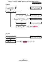
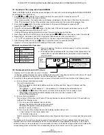
CN34
MCC-1402
Set Short-circuit-plug on the same
position as the P. C. board to replace.
Notes)
When
replacement
If short-circuit-plug is inserted in
CN34 of the P. C. board to replace,
re-use it in service P. C. board.
CN112
CN111
CN110
r
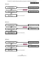
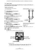
1 Readout of the setup data from EEPROM
(Data in EEPROM contents, which have been changed at the local site, are read out together with data in EEPROM
set at shipment from the factory.)
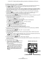
1. Push
SET
,
CL
, and
TEST
buttons of the remote controller at the same time for 4 seconds or more.
1
(Corresponded with No. in Remote controller)
When group operation, the master indoor unit address is displayed at the first time. In this time, the item code
(DN)
10
is displayed. The fan of the selected indoor unit operates and the louver starts swinging if any.
2. Every pushing
UNIT
button, the indoor unit address in the group are displayed successively.
2
Specify the indoor unit No. to be replaced.
3. Using the set temperature
/
buttons, the item code (DN) can be moved up and down one by one.
3
4. First change the item code (DN) from
10
to
01
.
(Setting of filter sign lighting time) Make a note of the set data displayed in this time.
5. Next change the item code (DN) using the set temperature
/
buttons. Also make a note of the set data.
6. Repeat item 5. and make a note of the important set data as shown in the later table (Ex.).
•
01
to
FF
are provided in the item code (DN). On the way of operation, DN No. may come out.
7. After finishing making a note, push
TEST
button to return the status to usual stop status.
6
(Approx. 1 minute is required to start handling of the remote controller.)
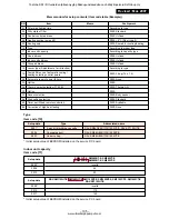
Minimum requirements for item code
DN
10
11
12
13
14
Contents
Type
Indoor unit capacity
Line address
Indoor address
Group address
1) Type and capacity of the indoor unit is necessary to set the revolutions
frequency of the fan.
2) If Line/Indoor/Group addresses differ from those before replacement, the
mode enters in automatic address setup mode and a manual resetting
may be required.
r
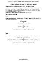
2 Replacement of service P.C. board
1. Replace the P.C. board with a service P.C. board.
In this time, setting of jumper line (cut) or setting of (short-circuit) connecting connectors on the former P.C. board
should be reflected on the service P.C. board. (See Appendix 1, page 4)
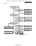
2. According to the system configuration, turn on power of the indoor unit with any method in the following items.
a) In case of single (individual) operation
Turn on the power supply.
1) Wait for completion of automatic address setup mode (Required time: Approx. 5 minutes) and then
proceed to
r
3.
(Line address = 1, Indoor address = 1, Group address = 0 (Individual) are automatically set.)
2) Push
SET
,
CL
, and
TEST
buttons of the remote controller at the same time for 4 seconds or more
(
1
operation), interrupt the automatic address setup mode, and then proceed to
r
3.
(Unit No.
ALL
is displayed.)
b) In case of group operation
Turn on power of the indoor unit of which P.C. board has been replaced with the service P.C. board with any
method in the following items.
1) Turn on power of the replaced indoor unit only.
(However, the remote controller is also connected.
Otherwise
r
3 operation cannot be performed.)
Same as 1) and 2) in item a).
2) Turn on power of the multiple indoor units including replaced indoor unit.
• Only 1 system for twin, triple, double twin
• For all units in the group
Wait for completion of automatic address setup mode (Required time: Approx. 5 minutes) and then proceed to
r
3.
* The master unit of a group may change by setup of automatic address. The line address/indoor address of the
replaced indoor unit are automatically set to the vacant addresses except addresses belonging to other indoor
units which have not been replaced. It is recommended to make a note that the refrigerant line which includes the
corresponding indoor unit and that the corresponding indoor unit is master or sub in the group control.
Toshiba SDI / DI tuotteiden jälleenmyyjä pääkaupunkiseudulla on Jäähdytinpalvelu RefGroup Oy
www.ilmalämpöpumput.com


