FILE NO. SVM-13072
No.
2
Part name
Front
cabinet
Procedure
Remarks
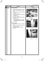
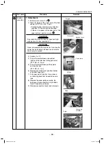
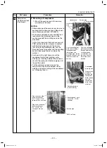
1. How to remove
1) Perform 1 of
1
.
2) Remove the screw between front cabinet
and side cabinet (right). (ST1T Ø4 × 8,
1 pc.)
3) Remove the screw between front cabinet
and inverter.
(ST1T Ø4 × 8, 2 pcs.)
4) Remove the screw between front cabinet
and bottom slab.
(ST1T Ø4 × 8, 3 pcs.)
5) Remove the screw between front cabinet
and motor base.
(ST1T Ø4 × 8, 2 pcs.)
s,EFTSIDEOFFRONTPANELISINSERTEDINTO
side cabinet (left). Remove by pulling
the upper part.
2. How to install
1) Insert front panel’s hook into side cabinet
(left).
2) Insert side cabinet (left)’s hook into front
cabinet’s corner hole.
3) Insert the removed screws to their
positions.
Motor base
Front cabinet
Corner hole
Hook
Corner hole
Hook
– 97 –
SVM-13072.indb 97
SVM-13072.indb 97
11/01/13 1:53 PM
11/01/13 1:53 PM

