– 31 –
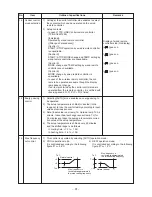
+4
+3
Tsc
Ta ˚C
Normal control
Max. frequency is
restricted to approximately
the rated cooling frequency
Tsh
–3
–4
Ta ˚C
Normal control
Max. frequency is
restricted to approximately
the rated heating frequency
No.
14
15
16
Item
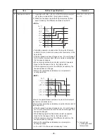
Central control
mode selection
Energy-saving
control
Max. frequency
cut control
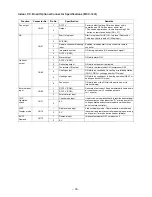
Outline of specifications
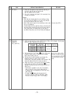
1) Setting at the central controller side enables to select
the contents which can be operated on the wired
remote controller.
2) Setup contents
• In case of TCC-LINK Central remote controller
(TCB-SC642TLE2)
[Individual]:
Operated by wired remote controller
([After-push precedence])
[Central 1]:
START / STOP operation by wired remote controller
is unavailable.
[Central 2]:
START / STOP, MODE change and TEMP. setting by
wired remote controller are unavailable.
[Central 3]:
MODE change and TEMP. setting by wired remote
controller are unavailable.
[Central 4]:
MODE change by wired remote controller is
unavailable.
• In case of the wireless remote controller, the con-
tents to be operated are same though the display
lamp does not change.
If an item prohibited by the central control mode is
operated from the remote controller, it is notified with
receiving sound Pi, Pi, Pi, Pi, Pi (5 times)
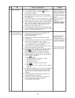
1) Selecting [AUTO] mode enables an energy-saving to
be operated.
2) The setup temperature is shifted (corrected) in the
range not to lose the comfort ability according to input
values of various sensors.
3) Data (Input value room temp. Ta, Outside temp. To, Air
volume, Indoor heat exchanger sensor temp. Tc) for
20 minutes are taken the average to calculate correc-
tion value of the setup temperature.
4) The setup temperature is shifted every 20 minutes,
and the shifted range is as follows.
In cooling time: +1.5 to – 1.0K
In heating time: –1.5 to +1.0K.
1) This control is operated by selecting [AUTO] operation mode.
2) COOL operation mode:
It is controlled according to the following
figure if To < 28°C.
3) HEAT operation mode:
It is controlled according to the following
figure if To > 15°C.
Remarks
Display at wired remote
controller side (No display)
[
] goes on.
[
] goes on.
[
] goes on.
[
] goes on.
Summary of Contents for RAV-SM1106BT-E
Page 18: ... 18 ...
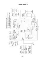
Page 19: ... 19 3 WIRING DIAGRAM ...
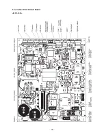
Page 34: ... 34 5 3 Indoor Print Circuit Board MCC 1631 ...
Page 89: ... 89 11 EXPLODED VIEWS AND PARTS LIST 11 1 RAV SM406BT E RAV SM456BT E RAV SM566BT E ...
Page 91: ... 91 11 2 RAV SM806BT E ...
Page 93: ... 93 11 3 RAV SM406BT TR RAV SM456BT TR RAV SM566BT TR ...
Page 95: ... 95 11 4 RAV SM806BT TR ...
Page 98: ... 98 11 6 RAV SM1106BT E RAV SM1406BT E RAV SM1606BT E ...
Page 100: ... 100 11 7 RAV SM1106BT TR RAV SM1406BT TR RAV SM1606BT TR ...


