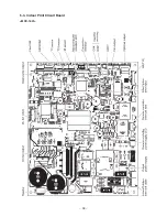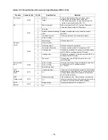
– 38 –
∗
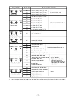
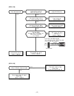
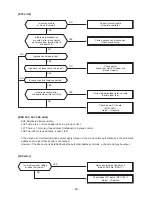
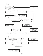
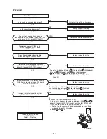
1: These are representative examples and the check code differs according to the outdoor unit to be combined.
⎫
⎪
⎬
⎪
⎭
⎫
⎬
⎭
⎫
⎬
⎭
⎫
⎪
⎬
⎪
⎭
⎫
⎬
⎭
⎫
⎪
⎬
⎪
⎭
⎫
⎪
⎬
⎪
⎭
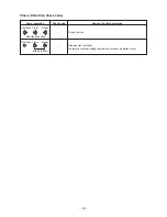
Lamp indication
Operation Timer
Ready
No indication at all
Operation Timer
Ready
Flash
Operation Timer
Ready
Flash
Operation Timer
Ready
Alternate flash
Operation Timer
Ready
Alternate flash
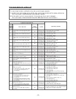
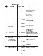
Check code
—
E01
E02
E03
E08
E09
E10
E18
E04
P10
P12
P03
P04
P05
P07
P15
P19
P20
P22
P26
P29
P31
Cause of trouble occurrence
Power supply OFF or miswiring between lamp indication unit and indoor unit
Receiving error
Receiving unit
Miswiring or wire connection error
Sending error
Communication stop
between receiving unit and indoor unit
Duplicated indoor unit No.
Setup error
Duplicated master units of remote controller
Communication error between CPUs on indoor unit P.C. board
Wire connection error between indoor units, Indoor power OFF
(Communication stop between indoor header and follower)
Miswiring between indoor unit and outdoor unit or connection erorr
(Communication stop between indoor and outdoor units)
Overflow was detected.
Protective device of indoor unit worked.
Indoor DC fan error
Outdoor unit discharge temp. error
Protective device of
∗
1
Outdoor high pressure system error
outdoor unit worked.
Negative phase detection error
Heat sink overheat error
Outdoor unit error
Gas leak detection error
4-way valve system error (Indoor or outdoor unit judged.)
Outdoor unit high pressure protection
Outdoor unit: Outdoor unit error
Protective device of
Outdoor unit: Inverter Idc operation
∗
1
Outdoor unit: Position detection error
outdoor unit worked.
Stopped because of error of other indoor unit in a group
(Check codes of E03/L03/L07/L08)
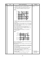
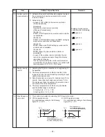
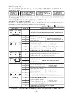
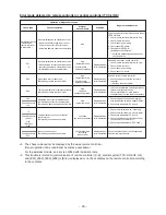
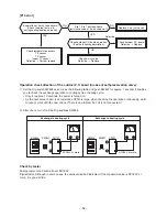
Outline of judgment
When one of the following phenomena appears, an error of the power relay (RY01) is considered; therefore
replace the P.C. board.
The primary judgment to check whether a trouble occurred in the indoor unit or outdoor unit is carried out with
the following method.
Method to judge the erroneous position by display panel of the indoor unit
(lamp display of the wireless receiving part)
The indoor unit monitors the operating status of the air conditioner, and the blocked contents of self-diagnosis
are displayed restricted to the following cases if a protective circuit works.
• The operation
started from the
remote controller.
• The fan stops immediately.
• The display on the remote
controller disappears.
After approx. 1minute
30 seconds, "Under setting"
is displayed.
The screen of the
remote controller
enters in STOP status.
→
→
→
: Go off, : Go on,
: Flash (0.5 sec.)
Summary of Contents for RAV-SM1106BT-E
Page 18: ... 18 ...
Page 19: ... 19 3 WIRING DIAGRAM ...
Page 34: ... 34 5 3 Indoor Print Circuit Board MCC 1631 ...
Page 89: ... 89 11 EXPLODED VIEWS AND PARTS LIST 11 1 RAV SM406BT E RAV SM456BT E RAV SM566BT E ...
Page 91: ... 91 11 2 RAV SM806BT E ...
Page 93: ... 93 11 3 RAV SM406BT TR RAV SM456BT TR RAV SM566BT TR ...
Page 95: ... 95 11 4 RAV SM806BT TR ...
Page 98: ... 98 11 6 RAV SM1106BT E RAV SM1406BT E RAV SM1606BT E ...
Page 100: ... 100 11 7 RAV SM1106BT TR RAV SM1406BT TR RAV SM1606BT TR ...


