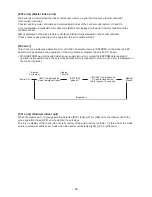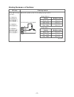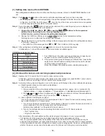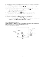
– 46 –
6-3. Diagnostic Procedure for Each Check Code (Indoor Unit)
Check code
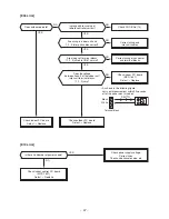
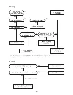
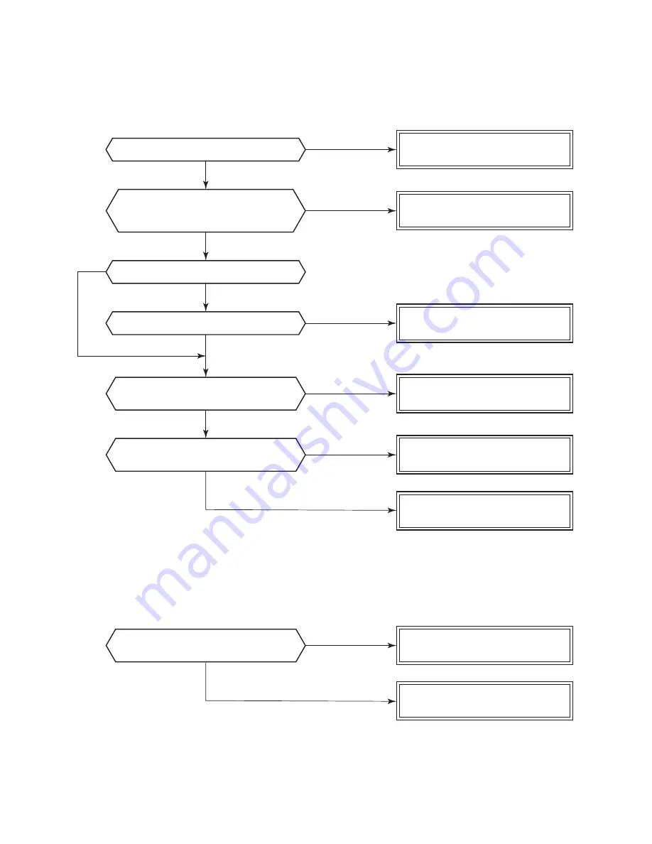
[E01 error]
Is inter-unit cable of A and B normal?
Is group control operation?
Is power of all indoor units turned on?
Is power supplied to remote controller?
AB terminal: Approx. DC18V
Are 2 remote controllers set
without header unit?
Are 2 header units set in
2 remote controllers?
Is there no disconnection or
contact error of connector on harness
from terminal block of indoor unit?
Check power connection of indoor unit.
(Turn on power again.)
Check indoor P.C. board (MCC-1631).
Defect
→
Replace
Check remote controller P.C. board.
Defect
→
Replace
Correct as a header unit
and a follower unit.
Check remote controller P.C. board.
Defect
→
Replace
Correct a header unit/a follower unit.
(Remote controller address connector)
Correct connection of connector.
Check circuit wiring.
Correct inter-unit cable
of remote controller
YES
YES
YES
YES
YES
YES
YES
NO
NO
NO
NO
NO
NO
NO
[E09 error]
Summary of Contents for RAV-SM1106BT-E
Page 18: ... 18 ...
Page 19: ... 19 3 WIRING DIAGRAM ...
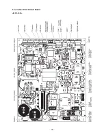
Page 34: ... 34 5 3 Indoor Print Circuit Board MCC 1631 ...
Page 89: ... 89 11 EXPLODED VIEWS AND PARTS LIST 11 1 RAV SM406BT E RAV SM456BT E RAV SM566BT E ...
Page 91: ... 91 11 2 RAV SM806BT E ...
Page 93: ... 93 11 3 RAV SM406BT TR RAV SM456BT TR RAV SM566BT TR ...
Page 95: ... 95 11 4 RAV SM806BT TR ...
Page 98: ... 98 11 6 RAV SM1106BT E RAV SM1406BT E RAV SM1606BT E ...
Page 100: ... 100 11 7 RAV SM1106BT TR RAV SM1406BT TR RAV SM1606BT TR ...

