background image

– 12 –

Concealed Duct High Static Pressure

Installation Manual

EN

5

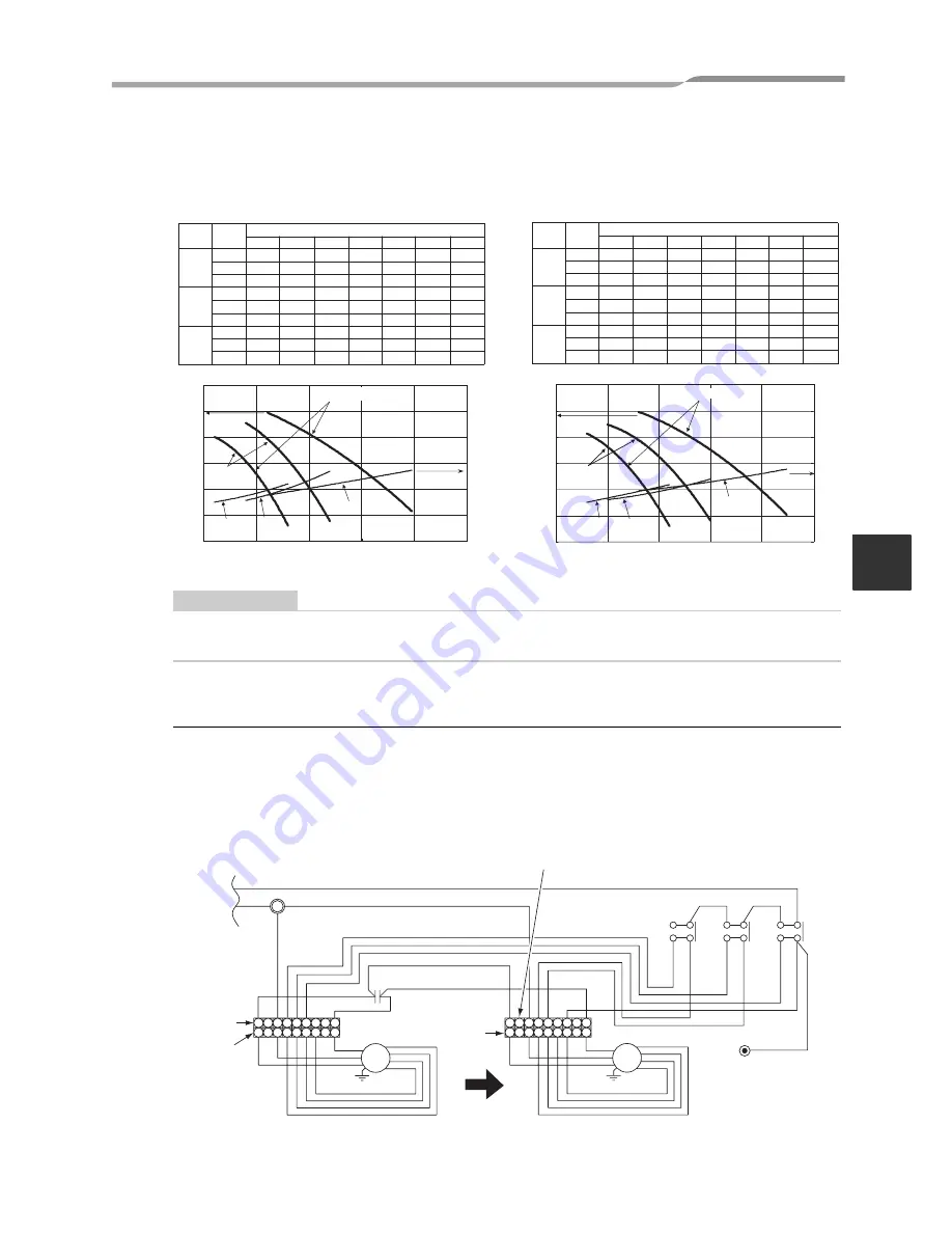
FAN CHARACTERISTICS

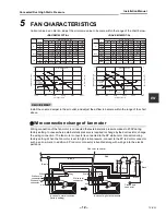
Current value as a criterion, adjust the air volume value to become within the range of the chart below.

REQUIREMENT

Install the volume damper in the air outlet, and adjust the airflow to become within the range of the chart 
above.

„

Wire connection change of fan motor

Wiring connection of the fan motor is connected that external static pressure makes to 200P during 
factory setting. In cases where external static pressure is required to change by the duct resistor, change 
the wiring connection. The fan motor connector is connected to the 9P white color connector during 
factory setting. When the fan motor is set to high static pressure, connect to the 9P red color connector 
such as arrow mark. In addition, 9P red color connector is bundled along with wirings into the electric 
parts box.

Hi

CMM

Med

CMM

Low

l/s

CMM

Fan-tap

m

3

/h

l/s

m

3

/h

m

3

/h

l/s

(unit)

Hi

CMM

Med

CMM

Low

l/s

CMM

Fan-tap

m

3

/h

l/s

m

3

/h

m

3

/h

l/s

(unit)

0

50

100

150

200

250

300

1,500

2,000

2,500

3,000

3,500

4,000

Static pressure (Pa)

0

1

2

3

4

5

6

Motor current (A)

Hi

Med.

Low

Hi

Med.

Low

High static pressure

Air volume(m3/h)

0

50

100

150

200

250

300

1,500

2,000

2,500

3,000

3,500

4,000

Static pressure (Pa)

0

1

2

3

4

5

6

Motor current (A)

Hi

Med.

Low

Low

Med.

Hi

Air volume(m3/h)

Normal 

Condition 

(ex factory)

Normal 

Condition 

(ex factory)

High static pressure

30

40

50

100

200

225

250

3,480 3,300 2,500 2,330 2,100

966

916

694

647

583

55.0

41.6

38.8

2,700 2,670 2,500 2,100 1,900

750

742

694

583

527

45.0

41.6

35.0

31.6

2,300 2,270 2,250 2,100 1,600

638

631

625

583

513

38.3

37.8

35.0

30.8

Static Pressure (Pa)

35.0

58.0

44.5

37.5

Static Pressure (Pa)

30

40

50

100

200

225

250

3,740 3,500 2,800 2,600 2,300
1,038

972

777

722

638

58.3

46.6

43.3

3,000 2,970 2,790 2,260 2,000

833

825

775

627

555

50.0

46.5

37.6

33.3

2,600

2,550 2,380 1,850

722

717

708

66

513

43.3

43.0

39.6

30.8

2,580

62.3

49.5

42.5

38.3

<RAV-SM1403DT-A>

<RAV-SM1603DT-A>

FM

RC

9

7

9

6

5

4

3

6

5

4

3

1

1

9

FM

6

5

7

4

3

1

9

5

7

3

1

4

4

43F3

43F2

6

3

5

2

4

6

3

5

43F1

4

6

3

5

White color 

connector

White color 

connector

White

Gray

Gray

Red

Ye

llo

w

Blue

In case of high static pressure

In case of normal condition 

(factory setting)

Red color connector

Brown

Brown

White

Gray

White

Ye

llo

w

Bl

u

e

Ora

nge

Bla

ck

Re

d

Gray

Ye

llow

Blue

Red

Red

Black

Black

O

range

Closed end 

connector

Ye

llo

w

Bl

u

e

Ora

nge

Bla

ck

Re

d

White

White color 

connector

12-EN

Summary of Contents for RAV-SM1403DT-A

Page 1: ...AIR CONDITIONER SPLIT TYPE Indoor Unit Model name Concealed Duct High Static Pressure Type RAV SM1403DT A RAV SM1603DT A Not accessible to the general public Installation Manual ...

Page 2: ...2 12 TROUBLE SHOOTING 34 Thank you very much for purchasing TOSHIBA Air Conditioner Please read this Installation Manual carefully before installing the Air Conditioner This Manual describes the installation method of the indoor unit For installation of the outdoor unit follow the Installation Manual attached to the outdoor unit ADOPTION OF NEW REFRIGERANT This Air Conditioner is a new type which ...

Page 3: ...r breaker before attempting any electrical work Make sure all power switches are off Failure to do so may cause electric shock Install the refrigerant pipe securely during the installation work before operating the air conditioner If the air conditioner is operated with the valve open and without the refrigerant pipe the compressor sucks air and the refrigeration cycle is overpressurized which may...

Page 4: ...op the compressor before disconnecting the refrigerant pipe If the refrigerant pipe is disconnected while the compressor is working with the valve open the compressor sucks air and the refrigeration cycle is overpressurized which may cause a burst or injury CAUTION New Refrigerant Air Conditioner Installation THIS AIR CONDITIONER ADOPTS THE NEW HFC REFRIGERANT R410A WHICH DOES NOT DESTROY OZONE LA...

Page 5: ...achines in a factory Oil adhering to the heat exchanger and resin part fan in the indoor unit may reduce the performance generate mist or dew drop or deform or damage resin parts Place where organic solvent is used nearby Place close to a machine generating high frequency Place where the discharged air blows directly into the window of the neighbor house Outdoor unit Place where noise of the outdo...

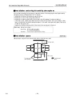
Page 6: ...ditionally attach the heat insulator to all positions of the air conditioner which come to contact with the high humidity atmosphere In this case arrange the side plate Check port so that it is easily removed Apply also a sufficient heat insulation to the duct and connecting part of the duct Installation space Unit mm Reserve space required for maintenance the indoor unit and service work Referenc...

Page 7: ...e of 400x800mm Notification of filter cleaning term setup The lighting term setup of the filter sign Notification of filter cleaning of the remote controller can be changed according to the condition of installation For setup method refer to Change of lighting term of filter sign and To secure better effect of heating in the Applicable controls of this Manual Flow direction of the air Concealed du...

Page 8: ...door units and human injury Do not put a heavy article on the indoor unit Even units are packaged Carry in the indoor unit as it is packaged if possible If carrying in the indoor unit unpacked by necessity be sure to use buffering cloth etc to not damage the unit To move the indoor unit hold the hooking metals 4 positions only Do not apply force to the other parts refrigerant pipe drain pan foamed...

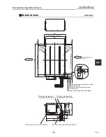
Page 9: ...of the air Hanging bolt pitch Refrigerant pipe gas side connecting external length Drain pipe connecting pipe external length Air outlet port flange Procured locally Refrigerant pipe liquid side connecting external length 42 50 97 53 380 25 32 490 600 Refrigerant pipe gas side connecting port 5 8 Ø15 9 Refrigerant pipe liquid side connecting port 3 8 Ø9 5 Electric parts box Cover is removable Drai...

Page 10: ...hang down the indoor unit Using a level vial check that four sides are horizontal Horizontal degree Within 5mm Check that four sides are horizontal using a level vial Horizontal degree Within 5mm REQUIREMENT Hang the unit in a horizontal position When unit is hanged to slant it may cause overflow of drainage Install the unit within the dimension according to the figure below Using level vial or vi...

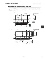
Page 11: ...aterial Galvanized steel plate thickness of 1 6 mm 25 65 15 10 25 316 296 10 12 807 271 757 256 20 20 276 25 12 256 25 15 65 8 Ø7 hole Air outlet port flange Inside dimension Inside dimension 24 Ø5 hole Incl hole Q ty at opposite side 10 Ø5 hole Incl hole Q ty at opposite side Unit mm 324 65 25 20 25 25 274 885 250 250 67 5 20 65 250 67 5 845 300 15 Air inlet port connecting flange 8 Ø7 hole Insid...

Page 12: ...lfunction of air conditioner or the water leakage NOTE Duct connecting of all units except outdoor unit are procured and enforced in locally Duct hose with heat insulation Flexible duct hanging band Air outlet chamber with heat insulation Air outlet port connecting flange Indoor unit High efficiency filter inserting port Pre filter inserting port Air inlet port connecting flange Air inlet chamber ...

Page 13: ...Med Low Hi Med Low High static pressure Air volume m3 h 0 50 100 150 200 250 300 1 500 2 000 2 500 3 000 3 500 4 000 Static pressure Pa 0 1 2 3 4 5 6 Motor current A Hi Med Low Low Med Hi Air volume m3 h Normal Condition ex factory Normal Condition ex factory High static pressure 30 40 50 100 200 225 250 3 480 3 300 2 500 2 330 2 100 966 916 694 647 583 55 0 41 6 38 8 2 700 2 670 2 500 2 100 1 900...

Page 14: ...ke descending slope of 1 50 to 1 100 and do not make up down bend and trap in the midway Also be sure to connect with adhesive the drain pipe connection from the air conditioner to avoid water leakage from the joint portion Do not apply the air vent This may cause water leakage according to overflow of drain water Make sure to insulate the all piping with heat insulation including drain pipe and m...

Page 15: ...in drain piping 100 or more Vinyl chloride pipe elbow VP25 Procured locally Soft socket Hard socket Flexible hose Accessory Hose band Accessory Vinyl chloride pipe socket VP25 Procured locally Indoor unit Vinyl chloride pipe VP25 Procured locally Do not use the adhesive to connect the supplied drain hose and drain pipe connection port of the indoor unit Unit mm 380 1 50 1 100 380 1 5m 2m Example f...

Page 16: ...ging occurs Connection of drain pipe Connect the hard socket local supply to the hard socket side of the attached flexible hose which has been installed Connect the drain pipes local supply successively to the connected the hard socket REQUIREMENT Using adhesive agent for vinyl chloride connect the hard vinyl chloride pipes certainly so that water does not leak It requires several times to dry and...

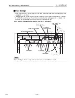
Page 17: ...k panel and perform it Heat insulating process After drain check using the attached heat insulator for drain connecting section wrap the flexible hose without clearance from the end of the drain pipe connecting port of the indoor unit Covering the attached heat insulator for drain connecting section wrap the drain pipe with heat insulator Procured locally without clearance Air outlet port Check po...

Page 18: ...he air in the connecting pipes using VACUUM PUMP 4 Check the gas leakage Connected points Pipe size Permissible Piping Length and Height Difference They vary according to the outdoor unit For details refer to the Installation Manual attached to the outdoor unit Flaring Cut the pipe with a pipe cutter Remove burrs completely Remaining burrs may cause gas leakage Insert a flare nut into the pipe and...

Page 19: ...r purge REQUIREMENT For the tools such as charge hose etc use those manufactured exclusively for R410A Refrigerant amount to be added For addition of the refrigerant add refrigerant R410A referring to the attached Installation Manual of outdoor unit Be sure to use a scale to charge the refrigerant of specified amount REQUIREMENT Charging an excessive or too little amount of refrigerant causes a tr...

Page 20: ...r Using the attached thermal insulation material apply the thermal insulation to the pipe connecting section of the indoor unit securely without gap REQUIREMENT Apply the thermal insulation to the pipe connecting section of the indoor unit securely up to the root without exposure of the pipe The pipe exposed to the outside causes water leak Wrap heat insulator with its slits facing up ceiling side...

Page 21: ...d inter connecting wires when peeling them Use the power cord and Inter connecting wire of specified thickness type and protective devices required REQUIREMENT For power supply wiring strictly conform to the Local Regulation in each country For wiring of power supply of the outdoor units follow the Installation Manual of each outdoor unit Never connect 220 240V power to the terminal blocks etc for...

Page 22: ...e storing part of the indoor unit electric parts otherwise the electric parts box cannot be drawn out in service time Mount the cover of the electric parts box without pinching wires CAUTION Power supply connector fixing band for twin Side C Space 4mm Select side C or D for the power cable clamping position referring to the following table according to the cable type and diameter Cable clamp can b...

Page 23: ...ion of the remote controller refer to the Installation Manual enclosed to in the remote controller Remote Controller Wiring Strip off approx 9mm the wire to be connected Non polarity 2 core wire is used for wiring of the remote controller 0 5mm to 2 0mm wires Wiring diagram Make a loop on the wire for margin of the length so that the electric parts box can be taken out during servicing L 1 3 10 50...

Page 24: ...ure 1 Push button and temp setup button simultaneously for at least 4 seconds After a while the display flashes as shown in the figure Confirm that the CODE No is 01 If the CODE No is not 01 push button to erase the display content and repeat the procedure from the beginning No operation of the remote controller is accepted for a while after button is pushed Procedure 2 Each time you push button i...

Page 25: ...tallation condition the lighting time of the filter sign Notification of filter cleaning can be changed Follow to the basic operation procedure 1 2 3 4 5 6 For the CODE No in Procedure 3 specify 01 For the Set data in Procedure 4 select the setup data of filter sign lighting time from the following table To secure better effect of heating When it is difficult to obtain satisfactory heating due to ...

Page 26: ...t numbers change as follows The fan of the selected unit runs 3 Adjust the power save setting by pushing TIME buttons Each push of the button changes the power level by 1 within the range from 100 to 50 The factory setting is 75 This indication may not be true for types other than 4 series outdoor unit Super Digital Inverter 4 Determine the setting by pushing button 5 Push button to complete the s...

Page 27: ...wing table 3 Pushing left side of the button select an indoor unit to be monitored The sensor temperatures of indoor units and their outdoor unit in the control group are displayed 4 Push button to return to the normal display 1 3 4 2 Indoor unit data CODE No Data name 01 Room temperature remote controller 02 Indoor unit intake air temperature TA 03 Indoor unit heat exchanger coil temperature TCJ ...

Page 28: ...its of other indoor units by wiring the inter unit wire of the remote controller When the power supply has been turned on the automatic address setup starts and which indicates that address is being set up flashes on the display part During setup of automatic address the remote controller operation is not accepted Required time up to the finish of automatic addressing is approx 5 minutes NOTE In s...

Page 29: ...an of the selected indoor unit operate Procedure 3 1 Using temp setup buttons specify CODE No 12 CODE No 12 Line address 2 Using timer time buttons change the line address from 3 to 2 3 Push button In this time the setup finishes when the display changes from flashing to lighting Procedure 4 1 Using temp setup buttons specify CODE No 13 CODE No 13 Indoor address 2 Using timer time buttons change t...

Page 30: ...own Check the position during operation stop Be sure to stop operation of the set Procedure 1 Push simultaneously buttons for 4 seconds or more After a while the display part flashes and the display appears as shown below In this time the position can be checked because fan of the indoor unit operate For the group control the indoor unit No is displayed as and fans of all the indoor units in the g...

Page 31: ...pushing button the indoor unit No in the group control is displayed in order Select the indoor unit of which setup is changed In this time the position of the indoor unit of which setup is changed can be confirmed because fan of the selected indoor unit operate Procedure 3 Using temp setup buttons specify CODE No d1 Procedure 4 Using timer time buttons select SET DATA 0001 Procedure 5 Push button ...

Page 32: ...order to prevent a serial operation the forced test run is released after 60 minutes have passed and returns to the usual operation CAUTION Do not use the forced test run for cases other than the test run because it applies an excessive load to the devices In case of wired remote controller Procedure 1 Keep button pushed for 4 seconds or more TEST is displayed on the display part and the selection...

Page 33: ...play disappears Ask an authorized service on maintenance professional to maintain the air conditioner 1 Take out the air filter Push the extrusion of the air filter to inside and pull out it to take out the air filter 2 Cleaning with water or vacuum cleaner If dirt is heavy clean the air filter by tepid water with neutral detergent or water After cleaning with water dry the air filter sufficiently...

Page 34: ...g water leakage and even compressor failure This product incorporates a drain pump If it is used in a place full of dust or oil mist the pump will be clogged and proper drainage is disabled Clean the drain pump periodically For how to clean the drain pump contact the dealer Maintenance List Part Unit Check visual auditory Maintenance Heat exchanger Indoor outdoor Dust dirt clogging scratches Wash ...

Page 35: ... The history can be confirmed from both operating status and stop status Procedure 1 When pushing and buttons at the same time for 4 seconds or more the following display appears If Service check is displayed the mode enters in the trouble history mode 01 Order of trouble history is displayed in CODE No Check code is displayed in CHECK Indoor unit address in which an error occurred is displayed in...

Page 36: ...oor follower unit regular communication error Indoor Indoor P C board Regular communication is not possible between header and follower indoor units or between twin header main and follower sub units Auto reset E31 IPDU communication error Outdoor Communication error between IPDU and CDB Entire stop F01 ALT Indoor unit heat exchanger sensor TCJ error Indoor Heat exchanger sensor TCJ indoor P C boa...

Page 37: ...r outdoor unit error Entire stop 1 Communication error between IPDU MCU and CDB MCU Entire stop 2 Abnormal temperature was detected by the heat sink temp sensor in IGBT L30 SIM Abnormal external input into indoor unit interlock Indoor External devices outdoor unit P C board Abnormal stop due to incorrect external input into CN80 Entire stop L31 SIM Phase sequence error etc Outdoor Power supply pha...

Page 38: ...utdoor unit inverter Idc activated Outdoor IGBT outdoor unit P C board inverter wiring compressor Short circuit protection for compressor drive circuit devices G Tr IGBT was activated Entire stop P29 ALT Outdoor unit position error Outdoor Outdoor unit P C board high pressure switch Compressor motor position error was detected Entire stop P31 ALT Other indoor unit error Indoor Another indoor unit ...

Page 39: ... 38 Concealed Duct High Static Pressure Installation Manual EN 38 EN ...

Page 40: ...EH99860501 ...

Reviews: