background image

30-EN

29-EN

– 15 –

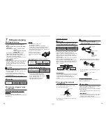
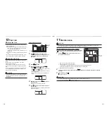
Heat insulation process

Apply heat insulation for the pipes separately at liquid 
side and gas side.


y

For the heat insulation to the pipes at gas side, 
be sure to use the material with heat-resisting 
temperature 120 °C or higher.


y

To use the attached heat insulation pipe, apply the 
heat insulation to the pipe connecting section of the 
indoor unit securely without gap.

REQUIREMENT


y

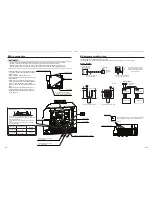
Apply the heat insulation to the pipe connecting 
section of the indoor unit securely up to the root 
without exposure of the pipe. (The pipe exposed 
to the outside causes water leak.)


y

Apply heat insulating materials to both the gas 
side and liquid side as shown:

Wrap the pipe with the attached heat insulator

without any gap between the indoor unit.

The seam must be faced upward

(ceiling side).

Flare nut

Indoor unit

Heat insulator

(Accessory)

Union

Banding band

(locally

procured)

Heat insulator

of the pipe

Refrigerant amount to be added

For addition of the refrigerant, add refrigerant “R410A” 
referring to the attached Installation Manual of outdoor 
unit.
Use a scale to charge the refrigerant of speci

fi

ed 

amount.

REQUIREMENT


y

Charging an excessive or too little amount of 
refrigerant causes a trouble of the compressor.

  Charge the refrigerant of speci

fi

ed amount.


y

A personnel who charged the refrigerant should 
write down the pipe length and the added 
refrigerant amount in the F-GAS label of the 
outdoor unit. It is necessary to 

fi

x the compressor 

and refrigeration cycle malfunction.

Open the valve fully

Open the valve of the outdoor unit fully. A 4 mm-
hexagonal wrench is required for opening the valve of 
liquid side.
For details, refer to the Installation Manual attached to
the outdoor unit.

Gas leak check

Check with a leak detector or soap water whether gas
leaks or not, from the pipe connecting section or cap of
the valve.

REQUIREMENT

Use a leak detector manufactured exclusively for 
HFC refrigerant (R410A).

Summary of Contents for RAV-SM2244DTP-E

Page 1: ...AIR CONDITIONER SPLIT TYPE Installation Manual Indoor Unit Model name For commercial use English Concealed Duct High Static Pressure Type RAV SM2244DTP E RAV SM2804DTP E ...

Page 2: ...onditioners made by Toshiba Carrier Corporation or alternatively he or she has been instructed in such matters by an individual or individuals who have been trained and is thus thoroughly acquainted with the knowledge related to this work Qualified service person The qualified service person is a person who installs repairs maintains relocates and removes the air conditioners made by Toshiba Carri...

Page 3: ...from heat Center of gravity Unit mm Use forklift to carry in the air conditioner units and use winch or hoist at installation of them 665 220 435 Center of gravity Warning indications on the air conditioner unit Warning indication Description WARNING ELECTRICAL SHOCK HAZARD Disconnect all remote electric power supplies before servicing WARNING ELECTRICAL SHOCK HAZARD Disconnect all remote electric...

Page 4: ...here is a danger of electric shocks if the circuit breaker is set to ON by mistake 1 Precautions for safety Only a qualified installer 1 or qualified service person 1 is allowed to undertake work at heights using a stand of 50 cm or more or to remove the intake grille of the indoor unit to undertake work Wear protective gloves and safety work clothing during installation servicing and removal Do n...

Page 5: ...ppliance in a place where it is directly exposed to the wind of air conditioner otherwise it may cause imperfect combustion Installation When the indoor unit is to be suspended the designated hanging bolts M10 or W3 8 and nuts M10 or W3 8 must be used Install the air conditioner securely in a location where the base can sustain the weight adequately If the strength is not enough the unit may fall ...

Page 6: ... earth wire Grounding work Incomplete grounding causes an electric shock Do not connect earth wires to gas pipes water pipes and lightning conductor or telephone earth wires After completing the repair or relocation work check that the earth wires are connected properly Install a circuit breaker that meets the specifications in the installation manual and the stipulations in the local regulations ...

Page 7: ...h the service valve left open and the compressor still operating will cause air or other gas to be sucked in raising the pressure inside the refrigeration cycle to an abnormally high level and possibly resulting in rupture injury or other trouble CAUTION New refrigerant air conditioner installation This air conditioner adopts the new HFC refrigerant R410A which does not destroy ozone layer The cha...

Page 8: ...spontaneously combust and start a fire y Locations where vapors from food oils are formed such as kitchens where food oils are used Blocked filters may cause the air conditioner s performance to deteriorate condensation to form the plastic parts to be damaged and other such problems to result y Locations near obstructions such as ventilation openings or lighting fixtures where the flow of the blow...

Page 9: ...rature 24 C wet bulb temperature Air volume Low air volume operation time 4 hours Installation space Unit mm Reserve sufficient space required for installation or service work 1 1 1 1 1 If there are enough space under the unit more than 1000mm the service door Ceiling opening is not necessary Space required for installation and servicing Ceiling 200 or more 25 1450 25 2500 or more Floor surface Se...

Page 10: ...nit Procure hanging bolts washer and nuts for installing the indoor unit these are not supplied Hanging bolt M10 or W3 8 4 pieces Nut M10 or W3 8 12 pieces Washer M10 8 pieces Installation of hanging bolt Use M10 hanging bolts 4 pcs locally procured Matching to the existing structure set pitch according to size in the unit external view as shown below New concrete slab Install the bolts with inser...

Page 11: ... at intervals of 1 5 to 2 meters to prevent flapping y Install the collective piping as shown in the following figure y Do not provide any air vents Otherwise the drain water will spout causing water to leak y Do not allow any force to be applied to the connection area with the drain pipe Heat insulator Downward slope 1 50 to 1 100 or more Support bracket As long as possible VP 30 Arched shape Tra...

Page 12: ...k remove the access panel and pour water then conduct the drain check Access plate Pour into the drain pan Heat insulating process y As shown in the figure cover the flexible hose and hose band with the attached heat insulator up to the bottom of the indoor unit tightly y Cover the drain pipe tightly with a heat insulator procured locally so that it overlaps with the attached heat insulator of the...

Page 13: ...h Air Flow m h Air Flow m h Standard Air Flow 3800 m h Standard Air Flow 3800 m h Standard Air Flow 4800 m h Standard Air Flow 4800 m h Mid 83Pa Mid 83Pa Mid 83Pa Mid 83Pa Mid 50Pa Mid 50Pa Mid 50Pa Mid 50Pa Mid 150Pa 117Pa Mid 150Pa 117Pa Mid 150Pa 117Pa Mid 150Pa 117Pa Mid 183Pa Mid 183Pa Mid 183Pa Mid 183Pa Mid 217Pa Mid 217Pa Mid 217Pa Mid 217Pa Mid 250Pa Mid 250Pa Mid 250Pa Mid 250Pa Low Low ...

Page 14: ... conditioner to fail or to leak Overview of duct connection NOTE Parts except air conditioner unit are to be locally procured Canvas joint Canvas joint Silencer chamber Air inlet Air filter Silencer chamber Air supply port Check port Air Conditioner Arrangement Unit mm Referring to the following dimensions manufacture duct at the local site Thickness of plate 0 8 mm 0 0 1 0 0 1 0 0 1 0 0 1 0 0 1 0...

Page 15: ...s useful for adjusting projection margin size A Tightening connection CAUTION Do not apply excessive torque Otherwise the nut may crack depending on the conditions Unit N m Outer dia of copper pipe Tightening torque 12 7 mm dia 50 to 62 5 0 to 6 2 kgf m q Tightening torque of flare pipe connections Pressure of R410A is higher than that of R22 Approx 1 6 times Therefore using a torque wrench tighte...

Page 16: ...nd locally procured Heat insulator of the pipe Refrigerant amount to be added For addition of the refrigerant add refrigerant R410A referring to the attached Installation Manual of outdoor unit Use a scale to charge the refrigerant of specified amount REQUIREMENT y Charging an excessive or too little amount of refrigerant causes a trouble of the compressor Charge the refrigerant of specified amoun...

Page 17: ...wires to the terminal blocks provide a trap and fix wires with the cord clamp y Run the refrigerant piping line and control wiring line in the same line y Do not turn on the power of the indoor unit until vacuuming of the refrigerant pipes completes Wiring 1 Figure below shows the wiring connections indoor power line and between the indoor and outdoor units and between the indoor units and remote ...

Page 18: ... off approx 9 mm the wire to be connected y Non polarity 2 core wire is used for wiring of the remote controller 0 5 mm to 2 0 mm wires Wiring diagram A B A B Terminal block for remote controller wiring of indoor unit Remote controller wire Locally procured Remote controller unit Terminal block System interconnection wire and remote controller wires 2 mm or less See the figure on the left for syst...

Page 19: ... display content and repeat the procedure from the beginning No operation of the remote controller is accepted for a while after button is pushed While air conditioners are operated under the group control ALL is displayed first When is pushed the indoor unit number displayed following ALL is the header unit Display content varies with the indoor unit model 2 Each time button is pushed indoor unit...

Page 20: ...m the following table SET DATA Filter sign term 0000 None 0001 150 H 0002 2500 H Factory default 0003 5000 H 0004 10000 H To secure better effect of heating When it is difficult to obtain satisfactory heating due to installation place of the indoor unit or structure of the room the detection temperature of heating can be raised Also use a circulator or other device to circulate heat air near the c...

Page 21: ...rant line system follow to Electrical connection y Wiring between lines is performed in the following procedure Connect the terminal block A B of the indoor unit connected with a remote controller to the terminal blocks A B of the indoor units of other indoor units by wiring the inter unit wire of the remote controller y When the power supply has been turned on the automatic address setup starts a...

Page 22: ... from 3 to 2 TIME buttons 3 Push button In this time the setup finishes when the display changes from flashing to lighting Indoor UNIT No before setup change is displayed 5 1 Specify CODE No 14 TEMP buttons CODE No 14 Group address 2 Change the SET DATA from 0001 to 0002 TIME buttons SET DATA Header unit 0001 Follower unit 0002 3 Push button In this time the setup finishes when the display changes...

Page 23: ... Push buttons simultaneously for 4 seconds or more when the air conditioner is not working After a while the display part flashes as shown below Check the Displayed CODE No is 10 y When the CODE No is other than 10 push button to erase the display and repeat procedure from the first step After pushing button operation of the remote controller is not accepted for approx 1 minute Display changes acc...

Page 24: ...or Heat y Do not run the air conditioner in a mode other than Cool or Heat y The temperature controlling function does not work during test run y The detection of check code is performed as usual 4 After the test run push button to stop a test run Display part is same as procedure 1 5 Push button to cancel release from the test run mode TEST disappears on the display and the status returns to a no...

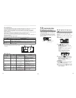
Page 25: ... is generated Filter Indoor Dust dirt breakage y Wash the filter with water when it is contaminated y Replace it when it is damaged Fan Indoor y Vibration balance y Dust dirt appearance y Replace the fan when vibration or balance is terrible y Brush or wash the fan when it is contaminated Air intake discharge grilles Indoor outdoor Dust dirt scratches Fix or replace them when they are deformed or ...

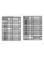
Page 26: ...sor problem Outdoor Outdoor temp sensor TO outdoor p c board Open circuit or short circuit of the outdoor air temp sensor was detected Operation continued Wired remote controller display Wireless remote controller Sensor block display of receiving unit Main problem parts Judging device Parts to be checked Check code description Air conditioner status Indication Operation Timer Ready GR GR OR Flash...

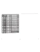
Page 27: ...der or the float switch was activated Entire stop P12 ALT Indoor DC fan problem Indoor Indoor DC fan problem e g overcurrent or lock up is detected Entire stop P15 ALT Gas leakage detected Outdoor There may be gas leakage from the pipe or connecting part Check for gas leakage Entire stop P19 ALT 4 way valve problem Outdoor Indoor 4 way valve indoor temp sensors TC TCJ An problem was detected due t...

Page 28: ...1117880399 TOSHIBA CARRIER THAILAND CO LTD 144 9 MOO 5 BANGKADI INDUSTRIAL PARK TIVANON ROAD TAMBOL BANGKADI AMPHUR MUANG PATHUMTHANI 12000 THAILAND ...

Reviews: