background image

13-EN

14-EN

– 7 –

6

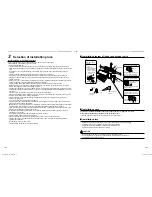
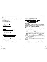
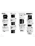
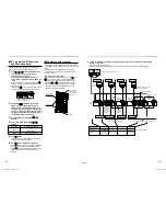
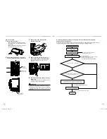
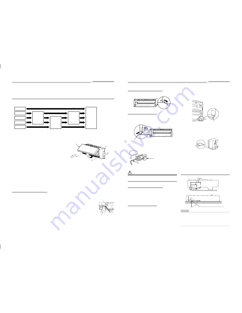
  Piping and drain hose installation


Piping and drain hose forming

*  

Apply heat-insulation for both refrigerant pipe and drain hose surely so that no dew generates inside of the 
equipment. (use polyethylene foam for insulating material.)

Piping 

preparation

Die-cutting 

front panel 

slit

Rear right

Rear left

Bottom left

Left

Bottom right

Removing 

front panel

Changing 

drain hose

1. Remove the front panel

The front panel must be removed for piping
connections in the left, bottom left, and rear left
directions.

• 

Open the air intake grille upward.

• 

Remove the four screws securing the front panel.

• 

Slightly open the lower part of the front panel, and
then pull the upper part of the front panel toward you
to remove it from the rear plate.

2. Die-cutting front panel slit

Cut out the slit on the leftward or right side of the front panel for the left or right connection and the slit on the 
bottom left or right side of the front panel for the bottom left or right connection with a pair of nippers.

3. Changing drain hose

For leftward connection, bottom-leftward connection and rear leftward connection’s piping, it is necessary to 
change the drain hose and drain cap.
Without changing the drain hose position, the indoor unit will not fit to the wall.

How to remove the drain hose

• 

The drain hose can be removed by removing the screw securing the drain hose and 
then pulling out the drain hose.

• 

When removing the drain hose, be careful of any sharp edges of steel plate. The edges 
can injuries.

• 

To install the drain hose, insert the drain hose 

fi

 rmly until the connection part contacts 

with heat insulator, and the secure it with original screw.

3

1

2

Front panel

Air intake grille

Drain hose

Heat insulator

How to remove the drains cap

Clip the drain cap by needle-nose pliers and pull out.

How to 

fi

 x the drains cap

1

  Insert hexagonal wrench (dia. 4 mm) in a 

centre head.

4 mm

2

  Firmly insert drains cap.

Insert a hexagon 

wrench (4 mm)

No gap

Do not apply lubricating oil 

(refrigerant machine oil) 

when inserting the drain cap.

Application causes 

deterioration and drain 

leakage from the plug.

 CAUTION

Firmly insert the drain hose and drain cap; otherwise, 
water may leak.

How to remove the drain hose

1

  Remove the front panel.

2

  Remove the screws of drain hose.

3

  Pull out the drain hose.

How to 

fi

 x the drain hose

1

  Place the drain hose in the speci

fi

ed 

position.

2

  Screw the drain hose to the indoor unit.

3

  Install the front panel.


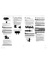
In case of left piping

After scribing slits of the front panel with a knife or a 
marking-off pin, cut them with a pair of nippers or an 
equivalent tool.

Slit


In case of bottom right or bottom left piping

After scribing slits of the front panel with a knife or a 
marking-off pin, cut them with a pair of nippers or an 
equivalent tool.

Slit


Left-hand connection with piping

Bend the connecting pipe so that it is laid within 43 
mm above the wall surface. If the connecting pipe 
is laid exceeding 43 mm above the wall surface, the 
indoor unit may unstably be set on the wall. When 
bending the connecting pipe, make sure to use a 
spring bender so as not to crush the pipe.

Bend the connection pipe within a radius of 30 mm.

To connect the pipe after installation of the unit (figure)

270 mm

230 mm

43 mm

80º

Use the handle of screwdriver, etc.

Outward form of indoor unit

(To the forefront of 

fl

are)

R 30 mm(use polish polyethylene 

core or the like for bending pipe.)

Gas side

Liquid side

NOTE

If the pipe is bent incorrectly, the indoor unit may 
unstably be set on the wall.
After passing the connecting pipe through the pipe 
hole, connect the connecting pipe to the auxiliary 
pipes and wrap the facing tape around them.

1111056499_(01)_EN.indb   7

1111056499_(01)_EN.indb   7

10/13/14   9:13 AM

10/13/14   9:13 AM

Summary of Contents for RAV-SM307KRTP-E

Page 1: ...l Type RAV SM307KRTP E RAV SM407KRTP E AIR CONDITIONER SPLIT TYPE Installation Manual For commercial use s Installation Manual English 1111056499_ 01 cover _EN indd 1 1111056499_ 01 cover _EN indd 1 10 13 14 9 57 AM 10 13 14 9 57 AM ...

Page 2: ...ation relocation and removal has the qualifications pertaining to this refrigerant handling and piping work as stipulated by the local laws and regulations and he or she is a person who has been trained in matters relating to refrigerant handling and piping work on the air conditioners made by Toshiba Carrier Corporation or alternatively he or she has been instructed in such matters by an individu...

Page 3: ...tion for electricians and from heat Warning indications on the air conditioner unit Warning indication Description WARNING ELECTRICAL SHOCK HAZARD Disconnect all remote electric power supplies before servicing WARNING ELECTRICAL SHOCK HAZARD Disconnect all remote electric power supplies before servicing WARNING Moving parts Do not operate unit with grille removed Stop the unit before the servicing...

Page 4: ...down or topple over or give rise to noise vibration water leakage or other trouble Carry out the specified installation work to guard against the possibility of high winds and earthquake If the air conditioner is not installed appropriately a unit may topple over or fall down causing an accident If refrigerant gas has leaked during the installation work ventilate the room immediately If the leaked...

Page 5: ...nied with the new refrigerant refrigerating oil has also been changed Therefore during installation work be sure that water dust former refrigerant or refrigerating oil does not enter the refrigerating cycle To prevent charging an incorrect refrigerant and refrigerating oil the sizes of connecting sections of charging port of the main unit and installation tools are changed from those for the conv...

Page 6: ...g under the unit installed that would be compromised by wetness If the drain has become blocked or when the humidity is over 80 condensation from the indoor unit will drip possibly causing damage to anything underneath In the case of the wireless type of system rooms with the inverter type of fluorescent lighting or locations exposed to direct sunlight The signals from the wireless remote controll...

Page 7: ...igure OK NO GOOD Not cooled well Good installation place Cooled well all over Bad installation place Screen Cutting a hole In case of installing the refrigerant pipes from the rear 1 Decide the hole position for piping at 100 mm from the arrow mark on the installation plate and drill a hole at a slight downward slant toward outdoor side 80 100 180 Ø65 mm 100 mm The centre of the pipe hole is above...

Page 8: ...y needle nose pliers and pull out How to fix the drains cap 1 Insert hexagonal wrench dia 4 mm in a centre head 4 mm 2 Firmly insert drains cap Insert a hexagon wrench 4 mm No gap Do not apply lubricating oil refrigerant machine oil when inserting the drain cap Application causes deterioration and drain leakage from the plug CAUTION Firmly insert the drain hose and drain cap otherwise water may le...

Page 9: ...from the installation plate pull the indoor unit toward you while pushing its bottom up at the specified parts Push Push 8 8 Drainage 1 Run the drain hose sloped downwards NOTE Hole should be made at a slight downward slant on the outdoor side 2 Put water in the drain pan and make sure that the water is drained out of doors 3 When connecting extension drain hose insulate the connecting part of ext...

Page 10: ... or too little amount of refrigerant causes a trouble of the compressor Charge the refrigerant of specified amount A personnel who charged the refrigerant should write down the pipe length and the added refrigerant amount in the F GAS label of the outdoor unit It is necessary to fix the compressor and refrigeration cycle malfunction 9 Open the valve fully Open the valve of the outdoor unit fully A...

Page 11: ...m CAUTION The remote controller wire and system interconnection wires cannot be parallel to contact each other and cannot be stored in the same conduits If doing so a trouble may be caused on the control system due to noise or other factor L1 L n L 2 L Remote controller Indoor unit Indoor unit Indoor unit Indoor unit Remote controller wiring max 8 units Remote controller inter unit wiring Wiring b...

Page 12: ... terminal 1 and 2 on terminal block respectively System interconnection wire 3 is not used 3 Connect the earth wire to the earth screw located on the underside of the electrical control box 4 Clamp the system interconnection wire with the cord clamp 5 Attach the terminal cover and the air intake grille to the indoor unit Cord clamp Earth screw System interconnection wiring Cord clamp Screw Screw E...

Page 13: ...re making settings CAUTION Set only the CODE No shown in the following table Do NOT set any other CODE No If a CODE No not listed is set it may not be possible to operate the air conditioner or other trouble with the product may result The displays appearing during the setting process differ from the ones for previous remote controllers AMT31E there are more CODE No 1 6 1 3 2 5 4 1 Push button and...

Page 14: ...NIT No 1 2 UNIT No 1 1 The fan of the selected unit runs 3 Adjust the power save setting by pushing TIME buttons Each push of the button changes the power level by 1 within the range from 100 to 50 The factory default is 75 Setting of power level in power saving mode 4 Determine the setting by pushing button 5 Push button to complete the setting Remote controller switch monitoring function This fu...

Page 15: ...ocedure Connect the terminal block A B of the indoor unit connected with a remote controller to the terminal blocks A B of the indoor units of other indoor units by wiring the inter unit wire of the remote controller When the power supply has been turned on the automatic address setup starts and which indicates that address is being set up flashes on the display part in about 3 minutes During setu...

Page 16: ...k the changed contents Address change check Before change 3 3 1 After change 2 2 2 Pushing button clears the contents of which setup was changed In this case procedure from 2is repeated Indoor UNIT No before setup change is displayed 7 After check of the changed contents push button setup is determined When button is pushed the display disappears and the status becomes the usual stop status when b...

Page 17: ...emote controller Use the optional wired remote controller Wiring for central control The terminal block for central control wiring 3 and 4 is the same as that for optional wired remote controller Connect the central control wire to the terminals 3 and 4 on the terminal block in the same way as the optional wired remote controller For details refer to the installation manual of the applicable centr...

Page 18: ...y connected the system will not operate or other errors may occur Centrally control the system by connecting to the TCC LINK central control system Setting central control addresses When air conditioners of the SDI DI series are connected to the TCC LINK central control system for central control using this product set the addresses of indoor units using the following procedure Completion of ELECT...

Page 19: ...ange For 30 or more refrigeration systems when they are used together with the SMMS series the number of refrigeration systems of the SMMS series is included The line address change setting procedure for up to the 29th refrigeration system is the same as that described in step 1 on the previous page Since all line addresses are set to 1 except for group control by the automatic address setup funct...

Page 20: ... 1 5 Push check button to cancel release from the test run mode TEST disappears on the display and the status returns to a normal When a test run is not performed properly When a test run is not performed properly refer to the error code and the part to be checked on Troubleshooting In case of wireless remote controller Forced test operation is performed in a different way REQUIREMENT For the oper...

Page 21: ...ce can extend the life of the product though it involves the owner s expense Failure to clean the indoor and outdoor units regularly will result in poor performance freezing water leakage and even compressor failure Inspection before maintenance Following inspection must be carried out by a qualified installer or qualified service person Part Inspection method Heat exchanger Access from inspection...

Page 22: ...t or short circuit of the heat exchanger sensor TCJ was detected Auto reset F02 ALT Indoor unit heat exchanger sensor TC error Indoor Heat exchanger sensor TC indoor P C board Open circuit or short circuit of the heat exchanger sensor TC was detected Auto reset F04 ALT Outdoor unit discharge temp sensor TD error Outdoor Outdoor temp sensor TD outdoor P C board Open circuit or short circuit of the ...

Page 23: ...vices outdoor unit P C board Abnormal stop due to incorrect external input into CN80 Entire stop L31 SIM Phase sequence error etc Outdoor Power supply phase sequence outdoor unit P C board Abnormal phase sequence of the 3 phase power supply Operation continued thermostat OFF P01 ALT Indoor unit fan error Indoor Indoor fan motor indoor P C board Indoor AC fan error fan motor thermal relay activated...

Page 24: ...1111056499 144 9 Moo 5 Bangkadi Industrial Park Tivanon Road Tambol Bangkadi Amphur Muang Pathumthani 12000 Thailand 1111056499_ 01 _EN indb 2 1111056499_ 01 _EN indb 2 10 13 14 9 13 AM 10 13 14 9 13 AM ...

Reviews: