background image

– 9 –

4

Installation

REQUIREMENT

Strictly comply with the following rules to prevent damage of the indoor units and human injury.
• Do not put a heavy article on the indoor unit. (Even units are packaged)
• Carry in the indoor unit as it is packaged if possible. If carrying in the indoor unit unpacked by necessity, use buffering 

cloth or other soft cloth to not damage the unit.

• To move the indoor unit, hold the hooking metals (4 positions) only.

Do not apply force to the other parts (refrigerant pipe, drain pan, foamed parts, or resin parts).

• Carry the package by two or more persons, and do not bundle it with plastic band at positions other than specified.

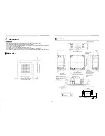
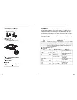
External view

13 to 20

Ceiling open dimension 580 to 594

13 to 20

Panel external dimension 620

13

 t

o

 2

0

13

 to

 2

0

C

eilin

op

e

dim

e

nsio

n

 5

80

 to

 5

9

4

P

an

el ex

te

rn

al dim

e

ns

ion

 6

20

External view

Unit: mm

23

+5 -0

146

191

95

147

105

55

235

105

235

320

214

256

(93) 40

132

173

257

70

Ø162

53

193

154

146

8

3

12

184

156

ØA

Ce

iling

 o

pe

n

 d

ime

n

sio

n 5

8

to 

59

4

Bottom face of ceiling

Wiring entry 

(for remote control)

Un

it ex

ter

n

al dim

e

nsio

n

 5

75

Refrigerant pipe connecting port 

(Gas side)

Refrigerant pipe connecting port 

(Liquid side)

Bottom face of ceiling

Unit external dimension 575

Electrical control box

Bottom face of ceiling

Ceiling panel

Hanging bolt M10 or W3/8 

(Procured by locally)

Drain discharge port 

(VP20)

Wiring entry 

(for power supply)

Knockout for simple 

OA for Ø100

40

0.

5

Hanging bolt pitch 496 to 538

Ceiling open dimension 580 to 594

Model RAV- 

A

SM30

9.5

SM40, 45, 56

12.7

Indoor unit

Bottom face of ceiling

Ha

ng

ing bo

lt p

itc

h 53

5

17

4.

5

325.

5

Ø6.4

2.5 to 9.5

17-EN

18-EN

Summary of Contents for RAV-SM307MUT-E

Page 1: ...English Indoor Unit Model name Compact 4 way Cassette type RAV SM307MUT E RAV SM407MUT E RAV SM457MUT E RAV SM567MUT E For commercial use AIR CONDITIONER SPLIT TYPE Installation Manual ...

Page 2: ...he Installation Manual attached to the outdoor unit ADOPTION OF R410A REFRIGERANT This Air Conditioner uses R410A an environmentally friendly refrigerant Contents 1 Precautions for safety 3 2 Accessory parts 7 3 Selection of installation place 7 4 Installation 9 5 Drain piping 11 6 Refrigerant piping 13 7 Electrical connection 14 8 Applicable controls 16 9 Test run 22 10 Maintenance 23 11 Troubles...

Page 3: ... or individuals who have been trained and is thus thoroughly acquainted with the knowledge related to this work Qualified service person The qualified service person is a person who installs repairs maintains relocates and removes the air conditioners made by Toshiba Carrier Corporation He or she has been trained to install repair maintain relocate and remove the air conditioners made by Toshiba C...

Page 4: ...ferent from the one specified for complement or replacement Otherwise abnormally high pressure may be generated in the refrigeration cycle which may result in a failure or explosion of the product or an injury to your body Before opening the intake grille of the indoor unit or service panel of the outdoor unit set the circuit breaker to the OFF position Failure to set the circuit breaker to the OF...

Page 5: ...ce any combustion appliance in a place where it is directly exposed to the wind of air conditioner otherwise it may cause imperfect combustion Installation When the indoor unit is to be suspended the designated hanging bolts M10 or W3 8 and nuts M10 or W3 8 must be used Install the air conditioner securely in a location where the base can sustain the weight adequately If the strength is not enough...

Page 6: ...eaker to the ON position You may receive an electric shock if the power is turned on without first conducting these checks If there is any kind of trouble such as check code display has appeared smell of burning abnormal sounds the air conditioner fails to cool or heat or water is leaking has occurred in the air conditioner do not touch the air conditioner yourself but set the circuit breaker to t...

Page 7: ... water dust former refrigerant or refrigerating oil enter the refrigerating cycle during installation work To prevent charging an incorrect refrigerant and refrigerating oil the sizes of connecting sections of charging port of the main unit and installation tools are changed from those for the conventional refrigerant Accordingly the exclusive tools are required for the R410A refrigerant For conne...

Page 8: ...e where drained water will not cause any problem Avoid installing in the following places Place exposed to air with high salt content seaside area or place exposed to large quantities of sulfide gas hot spring The unit should be used in these places special protective measures are needed A restaurant kitchen where a lot of oil is used or place near machines in a factory Oil adhering to the heat ex...

Page 9: ...re thick 200 200 15 or more 271 or more 1000 or more 271 or more 1000 or more 1000 or more An obstacle 15 or more 1 400 or more 560 or more 3 Check port 450 2 Check port 450 1000 or more Ceiling height Unit m When the height of the ceiling exceeds the distance of the item Standard 4 way in below table the warm air is difficult to reach the floor It is necessary to change the setup value of the hig...

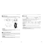
Page 10: ...o 20 Panel external dimension 620 13 to 20 13 to 20 Ceiling open dimension 580 to 594 Panel external dimension 620 External view Unit mm 23 5 0 146 191 95 147 105 55 235 105 235 320 214 256 93 40 132 173 257 70 Ø162 53 193 154 146 8 3 12 184 156 ØA Ceiling open dimension 580 to 594 Bottom face of ceiling Wiring entry for remote control Unit external dimension 575 Refrigerant pipe connecting port G...

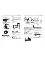
Page 11: ...ccording to size in the unit external view as shown below Hanging bolt M10 or W3 8 4 pieces Nut M10 or W3 8 12 pieces Indoor unit Panel fixing screw Installation pattern Accessory Installation pattern attachment hole New concrete slab Install the bolts with insert brackets or anchor bolts Steel flame structure Use existing angles or install new support angles Existing concrete slab Use a hole in a...

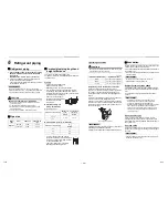
Page 12: ... le s s 5 Drain piping CAUTION CAUTION Following the Installation Manual perform the drain piping work so that water is properly drained and apply a heat insulation so as not to cause a dew drop Inappropriate piping work may result in water leakage in the room and wet of furniture Piping Heat insulating material Require the following materials for piping and heat insulating at site Flexible hose U...

Page 13: ... up 636 mm or less Underside of ceiling Indoor unit 300 mm or less Rising up 850 mm or less After the electric work has finished pour water during COOL mode operation If the electric work has not yet finished pull out the float switch connector CN34 Red from the electrical control box and check draining by plugging the single phase 220 240 V power to the terminal blocks and If doing so the drain p...

Page 14: ...depending on the conditions Tightening torque of flare pipe connections Pressure of R410A is higher than that of R22 Approx 1 6 times Use a torque wrench tighten the flare pipe connecting sections which connect the indoor and outdoor units of the specified tightening torque Incorrect connections may cause not only a gas leak but also a trouble of the refrigeration cycle Align the centres of the co...

Page 15: ...ss terminal etc Connection trouble in the places where the wire is connected in the middle may give rise to smoking and or a fire CAUTION CAUTION For power supply specifications follow the Installation Manual of outdoor unit Do not connect 220 240 V power to the terminal blocks for control wiring Otherwise the system will fail Do not damage or scratch the conductive core and inner insulator of pow...

Page 16: ...iple Double twin Indoor power inter unit wiring Indoor power inter unit wiring Outdoor side Remote controller Remote controller wiring Indoor side Indoor Outdoor connecting wires Wire connection REQUIREMENT Connect the wires matching the terminal numbers Incorrect connection causes a trouble Route the wire through the wire connection port of the indoor unit The low voltage circuit is provided for ...

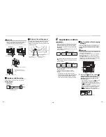
Page 17: ... Change the indoor unit settings as required Use the wired remote controller to change the settings The settings cannot be changed using the wireless remote controller sub remote controller or remote controller less system for central remote controller only Therefore install the wired remote controller to change the settings Basic procedure for changing settings Change the settings while the air c...

Page 18: ...ttings can also be changed with the switch on the indoor microcomputer P C board Once the setting is changed setting to 0001 or 0003 is possible however setting to 0000 requires a setting data change to 0000 using the wired remote controller separately sold with the normal switch setting factory default To restore the factory defaults To return the DIP switch settings to the factory defaults set S...

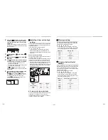
Page 19: ...n indoor unit to be set by pushing left side of the button Each time you push the button unit numbers change as follows The fan of the selected unit runs and the louvers start swinging 3 Select a louver you want to lock by pushing TEMP buttons 4 Select the wind direction of the louver you do not want to swing by pushing TIME buttons When 4 or 5 is selected dew drop may occur during cooling mode 5 ...

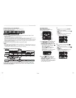
Page 20: ...er saving mode 1 3 4 2 4 Push button to return to the normal display Group control Simultaneous twin triple or double twin system A combination with an outdoor unit allows simultaneous ON OFF operation of the indoor units The following system patterns are available Two indoor units for the twin system Three indoor units for the triple system Four indoor units for the double twin system Twin system...

Page 21: ... Example of random setup After setup change of manual address Example of address setup change Outdoor unit Indoor unit Indoor unit Indoor unit Line address Group address Indoor address Address 1 1 1 Address 2 1 2 Address 2 2 2 Address 1 1 2 Address 2 1 2 Address 3 3 1 Procedure example 1 Single system Twin system Triple system Outdoor unit Indoor unit Indoor unit Indoor unit Remote controller Addr...

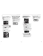
Page 22: ...ndoor UNIT No before setup change is displayed Indoor UNIT No before setup change is displayed To recognize the position of the corresponding indoor unit though the indoor UNIT No is known Check the position during operation stop Stop operation of the set 1 Push buttons simultaneously for 4 seconds or more After a while the display part flashes and the display appears as shown below In this time t...

Page 23: ... 9 Test run Before test run Before turning on the power supply carry out the following procedure 1 By using 500 V megger check that resistance of 1 MΩ or more exists between the terminal block 1 to 3 and the earth grounding If resistance of less than 1 MΩ is detected do not run the unit 2 Check the valve of the outdoor unit being opened fully To protect the compressor at activation time leave powe...

Page 24: ...recaution that the test run method in wireless remote controller differs from other indoor units Cooling test run Heating test run Set the temperature to 17 C with the temp setup buttons Set the temperature to 30 C with the temp setup buttons Cooling test run Heating test run After confirming a signal receiving sound beep immediately set the temperature to 18 C with the temp setup buttons After co...

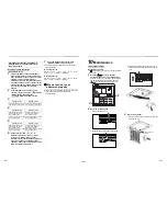
Page 25: ...poor performance freezing water leakage and even compressor failure Inspection before maintenance Following inspection must be carried out by a qualified installer or qualified service person Refer to the Service Manual for how to remove Maintenance List Parts Inspection method Heat exchanger Open the air intake grille to remove the bell mouth and the fan and then check the heat exchanger if there...

Page 26: ...ial communication trouble Indoor Indoor outdoor connecting wires indoor P C board outdoor P C board Serial communication trouble between indoor unit and outdoor unit Auto reset IPDU CDB communication trouble E08 Duplicated indoor addresses Indoor Indoor address setting trouble The same address as the self address was detected Auto reset E09 Duplicated header remote controllers Remote controller Re...

Page 27: ...upply Operation continued thermost at OFF P01 ALT Indoor unit fan trouble Indoor Indoor fan motor indoor P C board Indoor AC fan trouble fan motor thermal relay activated was detected Entire stop P03 ALT Outdoor unit discharge temp trouble Outdoor An trouble was detected in the discharge temp releasing control Entire stop Wired remote controller display Wireless remote controller Sensor block disp...

Page 28: ...EB99813501 ...
Reviews: