– 89 –
No. Part name
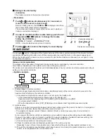
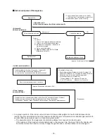
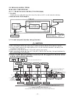
Procedure
Remarks
g
Control
P.C. board
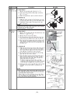
1. Detachment
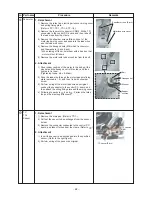
1) Remove the electric parts cover. (Refer to 1 of
d
)
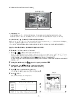
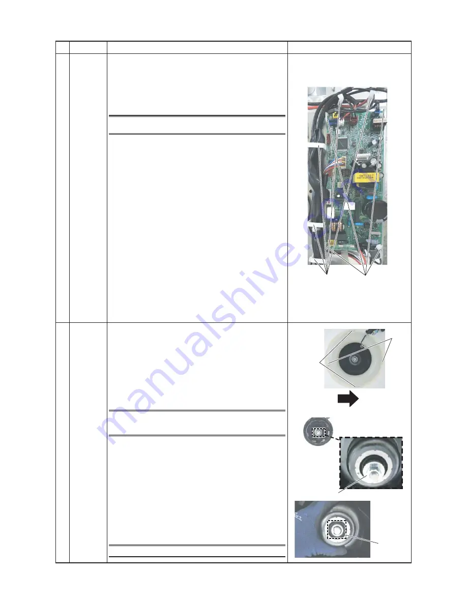
2) Remove connectors which are connected from the
control P.C. board to the other parts and then remove
wiring from the clamp.
NOTE
Unlock the lock of the housing part and then remove the
connector.
CN34 : Float switch (3P, Red)
CN41 : Remote controller (2P, Blue)
CN40 : Control wires (2P, Blue)
CN67 : Power supply wires (5P, Black)
CN101 : TC sensor (2P, Black)
CN102 : TCJ sensor (2P, Red)
CN104 : Room temp. (TA) sensor (2P, Yellow)
CN510 : Louver motor (20P, White)
CN504 : Drain pump (2P, White)
CN210 : Fan motor (7P, White)
CN22 : Earth wire (Tab terminal)
3) Unlock the locks of the card edge spacer (4 positions)
and remove the control P. C. board.
2. Attachment
1) Fix the control board to the card edge spacer
(4 positions).
2) Connect the removed connectors as original, which
were unconnected in item 1. Detachment, and fix the
wires with clamps.
3) Following to the work in
d
-2, attach the electric parts
covers as original.
h
Turbo fan
1. Detachment
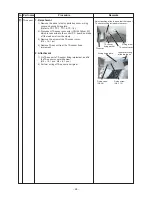
1) Remove the air intake grille. (Refer to 1 of
c
.)
2) Loosen the fix screws (2 positions) of the bell mouth,
rotate the bell mouth, and then take off it.
(Ø4 × 10, 2 pcs.)
3) Loosen the flange nut (M8) at the center part of the
turbo fan, and then take off (Counter clockwise)
* Supporting with hands, take off the turbo fan so that
it will not fall down.
NOTE
Use a box wrench for attachment and detachment of the
turbo fan. If using monkey wrench etc., the other parts may
be damaged in work.
2. Attachment
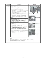
1) Match the D-cut of the motor shaft with the boss part
D-cut of the turbo fan, and then insert the turbo fan into
the motor shaft.
2) Tighten M8 nut with flange.
(Tightening torque of the turbo fan: 5.4+0.5, -0.2N•m)
3) Slide the Bell mouth removed in item 1-2) and attach it
then fix it with screws.
(Ø4 × 10, 2 pcs.).
4) Following to the work in item
c
-2, attach the air intake
grille as original.
NOTE
(Tightening torque of the turbo fan: 5.4 (+0.5, -0.2)N•m)
Fixing
S
lide lock
Lock rele
as
e direction
Fl
a
nge n
u
t (M8)
D-c
u
t
C
a
rd edge
s
p
a
cer
Cl
a
mp

