– 90 –
No. Part name
Procedure
Remarks
i
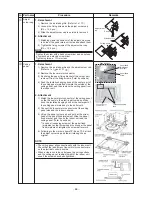
Drain pan
1. Detachment
1) Remove the ceiling panel and the electrical parts
covers.
(Refer to items
f
-1 and
d
-1.)
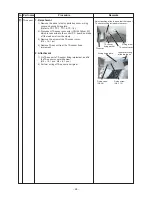
2) Remove the wiring cover. (Fixing screw Ø4 × 8, 3pcs.)
3) Remove the wiring fixing plate.
(Fixing screw Ø4 × 8, 1pc, Ø4 × 10, 1pc.)
4) Remove the connectors of the fan motor lead wire,
louver motor lead wire, and room temperature (TA)
sensor from the control P.C. bard, and then remove the
wiring from the clamp.
* Pull out the wires from the hole at the side face of the
electric parts.
CN210: Fan motor (7P, White)
CN510: Louver motor lead wire (20P, White)
CN104: TA (Room temperature) sensor (2P, Yellow)
5) Remove the drain plug of the drain pan, and extract the
stayed drain water.
* Be careful that water is extracted at a stretch when
taking off the drain plug.
* When taking off the drain plug, be sure to prepare a
bucket, etc. for spilled water.
6) Remove the fixing screws of the drain pan fixing
bracket.
(Ø4 × 8, 4 pcs.)
7) Using the both hands, hold the water-spilling port part
of the drain pan and then slowly pull out the foaming
parts firstly.
* As there is remained water in the drain pan, clear it
carefully.
2. Attachment
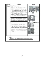
1) Arrange direction of the drain pan directly to the
foaming parts and insert it.
* Pass the fan motor lead wire through the inner side
of the drain pan.
2) Attach the fixing screws of the drain pan fixing
implement which was taken off in item 1-6).
(Ø4 × 12, 4 pcs.)
3) Insert the drain plug.
(Put the tool with thin top in the hole of the drain plug,
and then push the plug in.)
4) Perform wiring works to original arrangement, wiring of
the fan motor, louver motor lead wires, and the room
temperature (TA) sensor, and then attach the wiring
fixing bracket and the wiring cover.
5) Following to works in items
f
-2 and
d
-2, attach the
panel, electric parts cover as original.
Fixing
s
crew
s
Wiring cover
Fixing
s
crew (Ø4 × 8)
Dr
a
in pl
u
g
Dr
a
in p
a
n fixing
b
r
a
cket
Fixing
s
crew (4 po
s
ition
s
)
Dr
a
in pl
u
g
P
us
h in the dr
a
in pl
u
g
with the thin tip tool.
Wiring fixing pl
a
te
Fixing
s
crew
(Ø4 × 10)

