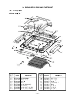
– 99 –
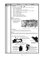
Piping holder
Lead wire
Piping holder r
Piping holder rib
Piping holder rib
2 screws
Soc
Socket of dr
et of drain pan
ain pan
Dr
Drain pan
ain pan
Socket of drain pan
Drain pan
2 screws
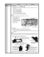
Hooking claw
Hooking claw
for drain pump
for drain pump
Drain pump assembly
Drain pump assembly
Drain hose
Drain hose
Fixing screw
Fixing screw
for drain pump
for drain pump
Hose band
Hose band
Hooking claw
for drain pump
Drain pump assembly
Drain hose
White marked position
White marked position
White marked position
Fixing screw
for drain pump
Hose band
No.
10
11
Part name
Drain pan
Drain pump
assembly
Procedure
1. Detachment
1) Perform works of procedure
4
-1 and
7
-1.
2) Remove the drain cap and extract drain water
accumulated in the drain pan.
NOTE)
When removing the drain cap, be sure to receive
drain water with a bucket, etc.
3) Take off screws fixing the drain pan to remove
the drain pan. (Ø4×10, 4 pcs.)
2. Attachment
1) Insert the drain cap into the drain pan.
NOTE)
Put a stick or others into hole at center of the drain
cap, and then insert the drain cap until it strikes on
the socket of the drain pan.
2) Draw each lead wire to the correct positions,
and then insert the drain pan into the main
unit.
NOTE)
Draw lead wires of the drain pump and the float
switch along the guide of the cabinet. Insert the drain
pan along the guides of sensors (TC1, TC2, TCJ)
and PMV lead wire.
The drain pan and each lead wire are not caught in;
otherwise water leakage may be caused.
3) Fix the drain pan with screws. (Ø4 × 10, 4 pcs.)
1. Detachment
1) Perform work of procedure
10
-1.
2) Pick up the hose band and slide it from the
pump connecting part to remove the drain
hose.
3) Take off screws (Ø4 × 10, 3 pcs.) fixing the
drain pump assembly, and then move hooking
claw (1 position) of the main body from the
drain pump assembly to remove the drain
pump assembly.
2. Attachment
1) Fix the drain pump assembly as original.
NOTE)
For fixing, use a hooking claw (1 position) and
screws (3 positions).
When screwing, be sure not to run on the hooking
claw at main body side.
2) Mount the drain hose and the hose band as
original.
NOTE)
Insert the drain hose up to the end of pump connect-
ing part, and then put the band at white marked
position of the hose.
Remarks


