background image

– 22 –

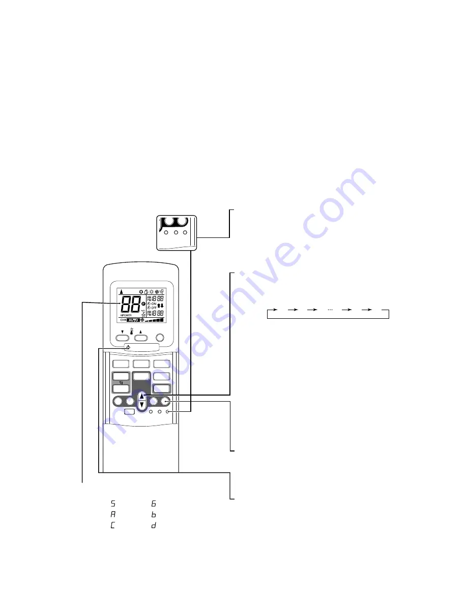
9-2. Self-Diagnosis by Remote Control

(Check Code)

(1) If the lamps are indicated as shown 00 to 03 in

Table 9-1-1, exchanger the self-diagnosis by the
remote control.

(2) When the remote control is set to the service

mode, the indoor controller diagnoses the
operation condition and indicate the information of
the self-diagnosis on the display of the remote
control with the check codes. If a fault is detected,
all lamps on the indoor unit will blink at 5 Hz and it
will beep for 10 seconds (Pi, Pi, Pi....). The timer
lamp usually blinks (5 Hz) during the self-diagnosis.

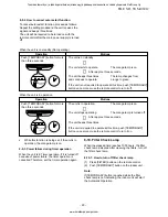
9-2-1. How to use remote control in service mode

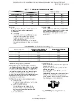
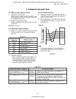
(1) Press [CHECK] button with a tip of pencil to set the

remote control to the service mode.

“00” is indicated on the display of the remote
control.

The timer lamp on the indoor unit blinks
continuously. (5 times per 1 sec.)

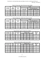
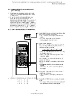
(2) Press [TIMER 

8

] button.

If there is no fault with a code, the indoor unit will
beep once (Pi) and the display of the remote
control will change as follows:

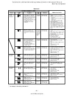
Check the unit with all 35 check codes (00 to 22).
as shown in Table 9-2-1.

Press [TIMER 

9

] button to change the check

code backwards.

If there is a fault, the indoor unit will beep for 10
seconds (Pi, Pi, Pi...).
Note the check code on the display of the remote
control.

2-digits alphanumeric will be indicated on the
display.

All lamps on the indoor unit will blink. (5 times
per 1 sec.)

(4) Press [START/STOP] button to release the service

mode.

The display of the remote control returns to as it
was before service mode was engaged.

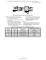
(3) Press [CLR] button. After service finish for clear

service code in memory.

“7F” is indicated on the display of the remote
control.

PRESET

FAN

MODE

Hi-POWER

ON

OFF

SET

CLR

ECO

AUTO

TIMER

CLOCK CHECK

RESET

FILTER

FIX

SWING

MEMO

START/STOP

A

B

AUTOA

SET

CLR

CLOCK CHECK

RESET

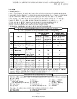
Alphanumeric characters are used for the check code.

is 5.

is 6.

is A.

is B.

is C.

is D.

00

01

1d

1E

02

22

FILE NO. SVM-06012

Toshiban lämmitys- ja jäähdytyslaitteiden jälleenmyyjä pääkaupunkiseudulla on Jäähdytinpalvelu RefGroup Oy

www.ilmalämpöpumput.com

Summary of Contents for RAV-SM562AT-E

Page 1: ...ONDITIONER UNDER CEILING CONSOLE TYPE RAV SM562XT E RAV SM562AT E RAV SM802XT E RAV SM802AT E April 2006 R410A Toshiban lämmitys ja jäähdytyslaitteiden jälleenmyyjä pääkaupunkiseudulla on Jäähdytinpalvelu RefGroup Oy www ilmalämpöpumput com ...

Page 2: ... EXPLODED VIEWS AND PARTS LIST 32 Note This Service Manual describes explanation for the Under Ceiling 1 console type indoor unit For the combined outdoor unit refer to the following Service Manual Outdoor unit Model name SVM to be referred RAV SMXX0AT E A03 007 RAV SPXXXAT E A03 014 RAV SMXX1AT E A05 001 RAV SMXX2AT E A05 018 FILE NO SVM 06012 Toshiban lämmitys ja jäähdytyslaitteiden jälleenmyyjä...

Page 3: ...imensions pipe Liquid side mm 6 4 9 5 Drain port mm VP16 Sound level dB A 43 39 36 46 42 37 Electrical characteristics Ceiling panel Sold separately Indoor unit Outdoor unit RAV SM562XT E RAV SM802XT E Cooling capacity Power supply kW 5 6 1 phase 230V 220 240V 50Hz 8 0 Cooling Running current A Power consumption kW Power factor EER Heating Running current W W Energy efficiency class Energy rating ...

Page 4: ... E Conditions Indoor DB20 C Outdoor DB7 C WB6 C Air flow High Pipe length 7 5m 230V 50 55 60 65 70 75 80 85 90 95 100 105 32 33 34 35 36 37 38 39 40 41 42 43 Outsoor temp C Capacity ratio Conditions Indoor DB27 C WB19 C Indoor air flow High Pipe length 7 5m 0 10 20 30 40 50 60 70 80 90 100 110 120 14 12 10 8 6 4 2 0 2 4 6 8 10 Outsoor temp C Capacity ratio Conditions Indoor DB20 C Indoor air flow ...

Page 5: ...late Mount plate M10 Suspention bolt Wireless remote control Knock out system 200 Min 1093 1015 742 450 20 20 330 165 Ø 7 4 70 Min 633 460 57 18 160 633 208 1093 UNDER CEILING CONSOLE INSTALLATION 3 FILE NO SVM 06012 Toshiban lämmitys ja jäähdytyslaitteiden jälleenmyyjä pääkaupunkiseudulla on Jäähdytinpalvelu RefGroup Oy www ilmalämpöpumput com ...

Page 6: ...pipe Gas side A Liquid side B 12 7 mm 6 4 mm Model 562XT E RAV SM 802XT E 15 9 mm 9 5 mm Note This Service Mamual describes explanation for the Under Ceiling 1 console type indoor unit For the combined outdoor unit refer to the following Service Manual Outdoor unit Model name SVM to be referred RAV SMXX0AT E A03 007 RAV SPXXXAT E A03 014 RAV SMXX1AT E A05 001 RAV SMXX2AT E A05 018 FILE NO SVM 0601...

Page 7: ... 2 3 4 5 6 7 8 9 10 1 2 3 4 5 6 7 8 9 10 INFRARED RAYS RECEIVE AND INDICATION PARTS SWITCH PCB MCC 1428B BRW RED ORN YEL PNK BLU BLU WHI BLU BLU BLU BLU BLU BLU BLU BLU CN13 CN07 CN100 CN402 J401 C01 R01 DB01 C02 DC12V IC03 C501 R405 R21 R22 SG01 F01 T6 3A FUSE 250VAC R09 R507 CR401 RY401 R506 CR502 RY501 CR501 CN05 CN03 CN01 CN10 CN11 CN401 CN23 FOR FLOAT SWITCH OPTION When you use float switch y...

Page 8: ... V 2 Grille motor MP35EA DC 12 V 3 Thermo sensor TA sensor 550 mm 10 kΩ at 25 C 4 Heat exchanger sensor TC sensor 6 mm 500 mm 10 kΩ at 25 C 5 Heat exchanger sensor TCJ sensor 6 mm 500 mm 10 kΩ at 25 C FILE NO SVM 06012 Toshiban lämmitys ja jäähdytyslaitteiden jälleenmyyjä pääkaupunkiseudulla on Jäähdytinpalvelu RefGroup Oy www ilmalämpöpumput com ...

Page 9: ...le on the market 6 REFRIGERANT R410A This air conditioner adopts the new refrigerant HFC R410A which does not damage the ozone layer The working pressure of the new refrigerant R410A is 1 6 times higher than conventional refrigerant R22 The refrigerating oil is also changed in accordance with change of refrigerant so be careful that water dust and existing refrigerant or refrigerating oil are not ...

Page 10: ...the flare processing correctly Use either a flare tool for R410A or conven tional flare tool Flare processing dimensions differ according to the type of flare tool When using a conven tional flare tool be sure to secure dimension A by using a gauge for size adjustment Fig 6 2 1 Flare processing dimensions 6 2 1 Processing of piping materials When performing the refrigerant piping installation care...

Page 11: ...ed to flare processing for R22 Nominal diameter Outer diameter mm Thickness mm Flare tool for R22 clutch type Dimension mm A B C D 1 4 6 35 0 8 9 1 9 2 6 5 13 17 3 8 9 52 0 8 13 2 13 5 9 7 20 22 1 2 12 70 0 8 16 6 16 0 12 9 23 26 5 8 15 88 1 0 19 7 19 0 16 0 25 29 Table 6 2 5 Flare and flare nut dimensions for R410A Nominal diameter Outer diameter mm Thickness mm Flare nut width mm Dimension mm A ...

Page 12: ... values designated by manufacturers Table 6 2 7 shows reference values Note When applying oil to the flare surface be sure to use oil designated by the manufacturer If any other oil is used the lubricating oils may deteriorate and cause the compressor to burn out Tightening torque of torque Nominal Outer diameter Tightening torque wrenches available on the market diameter mm N m kgf cm N m kgf m 1...

Page 13: ...re tool Pipe flaring Yes Note 1 2 Copper pipe gauge Flaring by for adjusting projection conventional flare Yes Note 1 Note 1 margin tool 3 Torque wrench Connection of Yes flare nut 4 Gauge manifold 5 Charge hose 6 Vacuum pump adapter Vacuum evacuating Yes 7 Electronic balance for Refrigerant charge Yes refrigerant charging 8 Refrigerant cylinder Refrigerant charge Yes 9 Leakage detector Gas leakag...

Page 14: ...the connecting hose to the cylinder and the connecting port of the electronic balance and charge liquid refrigerant For refrigerant charging see the figure below 1 Never charge refrigerant exceeding the specified amount 2 If the specified amount of refrigerant cannot be charged charge refrigerant bit by bit in COOL mode 3 Do not carry out additional charging When additional charging is carried out...

Page 15: ...derability 2 Phosphor bronze brazing filler Phosphor bronze brazing filler is generally used to join copper or copper alloy 3 Low temperature brazing filler Low temperature brazing filler is generally called solder and is an alloy of tin and lead Since it is weak in adhesive strength do not use it for refrigerant pipes 1 Phosphor bronze brazing filler tends to react with sulfur and produce a fragi...

Page 16: ...xide film from occurring in the pipe interior during brazing it is effective to proceed with brazing while letting dry Nitrogen gas N2 flow Never use gas other than Nitrogen gas 1 Brazing method to prevent oxidation 1 Attach a reducing valve and a flow meter to the Nitrogen gas cylinder 2 Use a copper pipe to direct the piping material and attach a flow meter to the cylinder 3 Apply a seal into th...

Page 17: ...lter Relay RY401 Louver ON OFF Signal Serial Signal Communication Hi POWER Display FILTER Sign Display PRE DEF Sign Display TIMER Display Louver Driver Functions Louver Control 3 minute Delay at Restart for Compressor Motor Revolution Control Processing Temperature Processing Timer Drain Pump ON OFF Serial Signal Communication Remote Control Infrared Rays 36 7 kHz 8 MHz M C U Indoor Unit Control P...

Page 18: ...ling heating or fan only depending on the room temperature If the AUTO mode is uncomfortable you can select the desired conditions manually Remote control Outline of control command STOP Air conditioner stops FAN Fan operation COOL Cooling operation DRY Dry operation HEAT Heating operation AUTO Automatic operation 1 1 1 3 2 5 2 1 5 1 0 5 0 5 0 M Preset temp C Room temp Preset temp Room temperature...

Page 19: ...4 C when the preset temperature is 24 C or more and A is the preset temperature when it is under 24 C 3 SUL means Super Ultra Low 4 Calculated from difference in motor speed between SUL and HIGH Fig 8 4 1 Cold draft preventing control 5 and 6 Table 8 4 1 A 4 A 4 A 8 A 8 46 45 34 33 33 21 32 20 2 6 5 Manual One of 5 steps L H Up to setting speed AUTO 4 SUL 3 SUL 1 Stop Fan 5 6 speed Starting period...

Page 20: ... 52 48 B L N M Tc C T1 Normal 1 minute 8 7 Louver control 1 Vertical air flow louver Position of veritcal air flow louver is automatically controlled according to the operation mode Besides position of vertical air flow louver can be arbitrarily set by pressing FIX button The louver position which is set by FIX button is stored in the microcomputer and the louver is automatically set at the stored...

Page 21: ...f the power is off Push the TEMPORARY button located in the center of the front panel continuously for three seconds The unit receives the signal and beeps three times The unit then restarts operating automatically in the event of power supply being accidentally shut down While the filter check lamp is on the TEMPORARY button has the function of filter reset button Operation Motions Push TEMPORARY...

Page 22: ...e indoor unit Note If TEMPORARY button is pushed while the filter check lamp is not indicating the indoor unit will start the Automatic Operation Operation Motions Push TEMPORARY button for more The unit is on standby than three seconds The unit starts to operate The orange lamp is on After approx three seconds The unit beeps three times The lamp changes from and continues to operate orange to gre...

Page 23: ...and parts 9 1 2 Troubleshooting procedure When a trouble occurred check the parts along with the following procedure NOTE For cause of a trouble power conditions or malfunc tion erroneous diagnosis of microcomputer due to outer noise is considered except the items to be checked If there is any noise source change the cables of the signal line to shield cables 9 1 3 Outline of Judgment A primary ju...

Page 24: ...eep once Pi and the display of the remote control will change as follows Check the unit with all 35 check codes 00 to 22 as shown in Table 9 2 1 Press TIMER 9 button to change the check code backwards If there is a fault the indoor unit will beep for 10 seconds Pi Pi Pi Note the check code on the display of the remote control 2 digits alphanumeric will be indicated on the display All lamps on the ...

Page 25: ...nks when error is defected The lamp on the indoor unit blinks when error is defected And it returns to the normal condition when recovering from errors The lamp on the indoor unit blinks when error is defected The lamp on the indoor unit blinks when error is detected 1 Check the indoor thermo sensor TA 2 Check the indoor P C board 1 Check the indoor heat exchanger sensor TC 2 Check the indoor P C ...

Page 26: ...played when error is detected Displayed when error is detected Displayed when error is detected Displayed when error is detected Displayed when error is detected 1 Outdoor unit does not completely operate Inter unit cable check correction of miscabling Outdoor P C board check P C board cables check Compressor case thermo check 2 In normal operation When outdoor sending serial LED Green flashes the...

Page 27: ...played when error is detected Displayed when error is detected Displayed when error is detected Displayed when error is detected Displayed when error is detected Displayed when error is detected Displayed when error is detected Displayed when error is detected 1 Inverter immediately stops even if restarted Compressor rare short 2 Check IPDU Cabling error 1 Compressor immediately stops even if rest...

Page 28: ...tance kΩ Temperature C Temperature C Caracteristics 2 20 10 0 10 20 40 30 50 40 30 20 10 0 0 10 10 30 20 40 50 60 70 TA sensor TC TCJ sensor Resistance kΩ 10 C or higher Resistance kΩ 10 C or lower Temperature C Caracteristics 3 200 100 20 10 0 0 10 0 10 20 40 30 50 60 70 TE TO TS sensor FILE NO SVM 06012 Toshiban lämmitys ja jäähdytyslaitteiden jälleenmyyjä pääkaupunkiseudulla on Jäähdytinpalvelu...

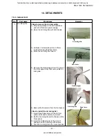
Page 29: ...rille 6 Remove the Panel arms from the Front panel How to install the Air inlet grille 1 Insert three Panel arms on the Air inlet grille and fix each securely by screws 2 Set the Air inlet grille arm to the axis of the Front panel 3 Insert the Grille stopper to the correct position and fix it securely with screws 4 Push the Air inlet grille to the correct position Air Inlet grille 10 DETACHMENTS A...

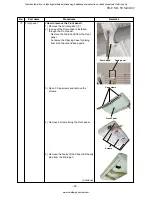
Page 30: ...ening base for piping from Front panel and keep parts 3 Open 3 Cap screws and remove the screws 4 Remove 5 screws fixing the Front panel 5 Remove the hooks of the Panel LED nearly side from the Drain pan Front panel Continue Drain band Drain panel Cap screws Front Panel Screws FILE NO SVM 06012 Toshiban lämmitys ja jäähdytyslaitteiden jälleenmyyjä pääkaupunkiseudulla on Jäähdytinpalvelu RefGroup O...

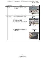
Page 31: ... into the Back body 4 Fix 8 screws and close 3 Cap screws 5 Install the Drain band into the Front panel 6 Check the gap between the Front panel and the Back body 3 How to remove the Drain pan 1 Remove the Air inlet grille and the Front panel 1 2 2 Remove the Louver motor from the Drain pan 3 Remove the shaft of Horizontal louver 4 Remove the LED base and Electrical wire 5 Remove the TA sensor wire...

Page 32: ...rew after the Back body is fixed 5 How to remove the Refrigeration assembly 1 Remove the Air inlet grille the Front panel and the Drain pan assembly 1 2 3 2 Stop the gas at the Outdoor unit 3 Remove 2 pipes from the Refrigeration assembly 4 Remove the TC sensor and TCJ sensor from holder 5 Remove the pipe holder 6 Remove the earth wire Drain pan assembly Electrical parts assembly Refrigeration ass...

Page 33: ... 3 Remove the Fan covers 4 Remove the Motor band with holding the Fan motor and then remove the Fan motor with the Multi blade fans 5 Unfasten the Set screw and remove the Multi blade fans Refrigeration assembly Multiblade fan and Fan motor Fan cover Motor band Motor 2 Connectors Multi blade fan 2 Screws FILE NO SVM 06012 Toshiban lämmitys ja jäähdytyslaitteiden jälleenmyyjä pääkaupunkiseudulla on...

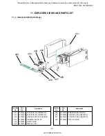
Page 34: ...60002 TERMINAL BLOCK 3P 404 43T62003 CORD CLAMP 405 43T69315 DISPLAY UNIT Location Part Description No No 406 43T50302 TEMPERATURE SENSOR 407 43T69564 PC BOARD RAV SM562XT E 407 43T69565 PC BOARD RAV SM802XT E 408 43T08349 SWITCH COVER 401 402 403 404 405 406 407 408 FILE NO SVM 06012 Toshiban lämmitys ja jäähdytyslaitteiden jälleenmyyjä pääkaupunkiseudulla on Jäähdytinpalvelu RefGroup Oy www ilma...

Page 35: ...ion No No 219 43T03339 BACK BODY ASSY 220 43T09314 VERTICAL LOUVER 221 43T49303 PIPE HOLDER 222 43T19324 COVER BODY L 223 43T19325 COVER BODY R 224 43T19328 COVER BODY LD 225 43T19326 BUSH BODY R 226 43T19327 BUSH BODY D 227 43T82308 PLATE INSTALLATION 228 43T60314 TERMINAL COVER 229 43T62303 CONNECTOR COVER 230 43T83003 HOLDER REMOTE CONTROLLER 231 43T69309 WRIRELESS REMOCON 233 43T49326 FLEXIBLE...

Page 36: ... 144 9 MOO 5 BANGKADI INDUSTRIAL PARK TIVANON ROAD TAMBOL BANGKADI AMPHUR MUANG PATHUMTHANI 12000 THAILAND Toshiban lämmitys ja jäähdytyslaitteiden jälleenmyyjä pääkaupunkiseudulla on Jäähdytinpalvelu RefGroup Oy www ilmalämpöpumput com ...

Reviews: