– 49 –
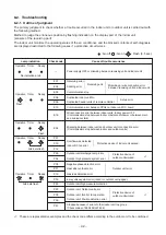
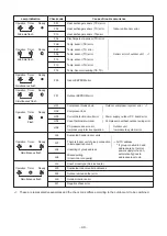
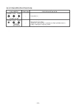
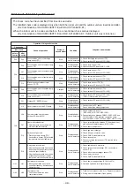
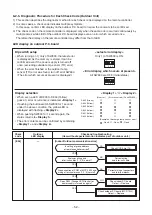
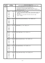
Error mode detected by outdoor unit
The check code has been ramified from
4
series and after.
The ramified check code is displayed only when both the indoor unit and the outdoor unit are
4
series and after.
(Ex. Combination of RAV-SM140
4
UTP-E with RAV-SP140
4
AT8-E1)
When the indoor unit is 3 series and before, the conventional check code is displayed.
(Ex. Combination of RAV-SM140
8
CTP-E and RAV-SP140
4
AT8-E1: Outdoor unit only is
4
series.)
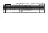
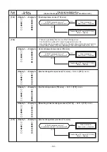
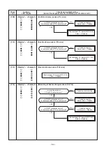
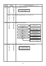
Operation of diagnostic function
Check code
Indoor unit
before
after
3 series 4 series
F04
F04
F06
F07
F06
F12
F15
F08
F08
F13
F31
L10
L29
L29
P07
P15
P19
H01
H01
H02
H02
Cause of operation
Disconnection, short of discharge
temp. sensor (TD)
Disconnection, short of outdoor temp.
sensor (TE)
Disconnection, short of outdoor temp.
sensor (TL)
Disconnection, short of suction temp.
sensor (TS)
Miss-mounting of outdoor temp.
sensor (TE, TS)
Disconnection, short of outside temp.
sensor (TO)
Disconnection, short of heat sink
temp. sensor (TH)
Outdoor P.C. EEPROM error
Unset jumper of service P.C. board
Communication error between
outdoor P.C. board MCU
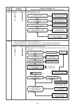
Heat sink overheat error
∗
Heat sink temp. sensor detected
over specified temperature.
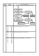
Detection of gas leak
∗
Discharge temp. sensor (TD),
Suction temp. sensor (TS) detected
temperature over specified temp.
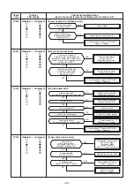
4-way valve inverse error
∗
After heating operation has started,
indoor heat exchanger temp. lowers
under the specified temp.
∗
After heating operation has started,
outdoor heat exchanger / suction
temp. rises over the specified temp.
Compressor break down
∗
Although operation has started,
operation frequency decreases and
operation stops.
Compressor lock
* Over-current detection after
compressor start-up
Status of
air conditioner
Stop
Stop
Stop
Stop
Stop
Continue
Stop
Stop
Stop
Stop
Stop
Stop
Stop
Stop
Stop
Condition
Displayed when
error is detected
Displayed when
error is detected
Displayed when
error is detected
Displayed when
error is detected
Displayed when
error is detected
Displayed when
error is detected
Displayed when
error is detected
Displayed when
error is detected
Displayed when
error is detected
Displayed when
error is detected
Displayed when
error is detected
Displayed when
error is detected
Displayed when
error is detected
Displayed when
error is detected
Displayed when
error is detected
Judgment and measures
1. Check discharge temp. sensor (TD).
2. Check outdoor P.C. board (MCC-1599).
1. Check temp. sensor (TE).
2. Check outdoor P.C. board (MCC-1599).
1. Check temp. sensor (TL).
2. Check outdoor P.C. board (MCC-1599).
1. Check suction temp. sensor (TS).
2. Check outdoor P.C. board (MCC-1599).
1. Check temp. sensor (TE, TS).
2. Check outdoor P.C. board (MCC-1599).
1. Check outside temp. sensor (TO).
2. Check outdoor P.C. board (MCC-1599).
1. Check outdoor P.C. board (MCC-1599).
(Q201 is incorporated in TH sensor.)
1. Check outdoor P.C. board (MCC-1599).
1. Outdoor service P.C. board
Check model type setting jumper wire.
1. Check outdoor P.C. board
(MCC-1596, MCC-1597, MCC-1599).
2. Connection check between CN802 of MCC-1599 and
CN504 of MCC-1597, and also connection check
between CN505 of MCC-1597 and CN851 of MCC-1596.
1. Check screw tightening between PC. Board and heat
sink and check radiator grease (MCC-1596).
2. Check heat sink blast path.
1. Check gas leak, recharge
2. Check full open of service valve.
3. Check PMV (Pulse Motor Valve).
4. Check broken pipe.
5. Check discharge temp. sensor (TD), suction temp.
sensor (TS).
1. Check operation of 4-way valve.
2. Check outdoor heat exchanger (TE), suction temp.
sensor (TS).
3. Check indoor heat exchanger sensor (TC).
4. Check 4-way valve coil.
5. Check PMV (Pulse Motor Valve).
1. Check power supply voltage. (AC342 to 457V)
2. Overload operation of refrigerating cycle
1. Trouble of compressor (Lock, etc.): Replace compressor.
2. Wiring error of compressor (Open phase)

