– 15 –
■
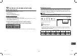
Existing piping
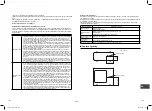
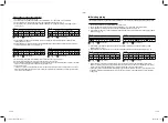
The following settings are required when using a pipe Ø3/4” (19.1 mm) as the existing piping at the gas pipe side.
Steps taken to support existing piping
1. Set the circuit breaker to the ON position to turn on the power.
2. Check that the LED displays are placed in their initial status. If not, place them in the initial status.
3. Hold down SW01 for at least 5 seconds, and check that D804 flashes slowly. (Fig. 5)
4. Press SW01 four times to set the LED displays (D800 to D805) to the “LED displays for existing piping settings”
shown below. (Fig. 6)
(Fig. 5)
LED displays indicated when step 3 is taken
D800
D801
D802
D803
D804
D805
: ON, : OFF, : Slow flashing
(Fig. 6)
LED displays for existing piping settings
D800
D801
D802
D803
D804
D805
: ON, : OFF, : Rapid flashing
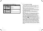
5. Press SW02 to set D805 to rapid flashing. (Each time SW02 is pressed, D805 is switched between rapid
flashing and OFF.) (Fig. 7)
6. Hold down SW02 for at least 5 seconds, and check that D804 flashes slowly and that D805 lights. (Fig. 8)
(Fig. 7)
LED displays indicated when step 5 is taken
D800
D801
D802
D803
D804
D805
: ON, : OFF, : Rapid flashing
(Fig. 8)
LED displays indicated when step 6 is taken
D800
D801
D802
D803
D804
D805
: ON, : OFF, : Slow flashing
7. Hold down SW01 and SW02 simultaneously for at least 5 seconds to return the LED displays to the initial
status. The existing piping is now supported by taking the above steps. In this status, the heating capacity may
decrease during heating depending on the outside air temperature and indoor temperature.
*
If there is any reason to doubt whether establishing support was successful in the course of this operation, hold
down SW01 and SW02 simultaneously for at least 5 seconds to return to the initial status, and then repeat the
setting steps.
Steps taken to recover the refrigerant
1. Operate the indoor unit in the fan mode.
2. Check that the LED displays are placed in their initial status. If not, place them in the initial status.
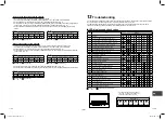
3. Hold down SW01 for at least 5 seconds, and check that D804 flashes slowly. (Fig. 1)
4. Press SW01 once to set the LED displays (D800 to D805) to the “refrigerant recovery LED display” shown
below. (Fig. 2)
(Fig. 1)
LED displays indicated when step 3 is taken
D800
D801
D802
D803
D804
D805
: ON, : OFF, : Slow flashing
(Fig. 2)
Refrigerant recovery LED display
D800
D801
D802
D803
D804
D805
: ON, : OFF, : Rapid flashing
5. Press SW02 to set D805 to rapid flashing. (Each time SW02 is pressed, D805 is switched between rapid
flashing and OFF.) (Fig. 3)
6. Hold down SW02 for at least 5 seconds, and when D804 flashes slowly and D805 lights, the forced cooling
operation is started. (Max. 10 minutes) (Fig. 4)
(Fig. 3)
LED displays indicated when step 5 is taken
D800
D801
D802
D803
D804
D805
: ON, : OFF, : Rapid flashing
(Fig. 4)
LED displays indicated when step 6 is taken
D800
D801
D802
D803
D804
D805
: ON, : OFF, : Slow flashing
7. After operating the system for at least 3 minutes, close the valve on the liquid side.
8. After the refrigerant has been recovered, close the valve on the gas side.
9. Hold down SW01 and SW02 simultaneously for at least 5 seconds. The LED displays are returned to the initial
status, and the cooling operation and indoor fan operation stop.
10. Turn off the power.
*
If there is any reason to doubt whether the recovery was successful in the course of this operation, hold down
SW01 and SW02 simultaneously for at least 5 seconds to return to the initial status, and then repeat the steps
for recovering the refrigerant.
29-EN
30-EN
1131601101 EN FR ES.indb 15
1131601101 EN FR ES.indb 15
4/8/2565 BE 10:14
4/8/2565 BE 10:14

