background image

– 3

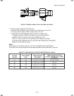
1

 –

FILE NO. SVM-13047

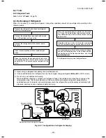
Gauge manifold

]


n

o

h

p

i

s


t

u

o

h

t

i

w


r

e

d

n

i

l

y

C


[

]


n

o

h

p

i

s


h

t

i

w


r

e

d

n

i

l

y

C


[

OUTDOOR unit

Gauge manifold

OUTDOOR unit

Refrigerant

cylinder

Electronic

balance

Refriger

ant

cylinder

Electronic

balance

Siphon

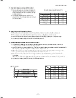
1) Be sure to make setting so that 

liquid

 can be charged.

2) When using a cylinder equipped with a siphon, liquid can be charged without turning it upside down.

It is necessary for charging refrigerant under condition of liquid because R410A is mixed type of refrigerant.

Accordingly, when charging refrigerant from the refrigerant cylinder to the equipment, charge it turning the
cylinder upside down if cylinder is not equipped with siphon.

R410A refrigerant is HFC mixed refrigerant.

Therefore, if it is charged with gas, the
composition of the charged refrigerant changes
and the characteristics of the equipment varies.

Fig. 6-4-2

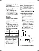
6-5. Brazing of Pipes

6-5-1. Materials for Brazing

1. Silver brazing filler

Silver brazing filler is an alloy mainly composed
of silver and copper.

It is used to join iron, copper or copper alloy, and
is relatively expensive though it excels in solder-
ability.

2. Phosphor bronze brazing filler

Phosphor bronze brazing filler is generally used
to join copper or copper alloy.

3. Low temperature brazing filler

Low temperature brazing filler is generally called
solder, and is an alloy of tin and lead.

Since it is weak in adhesive strength, do not use
it for refrigerant pipes.

1) Phosphor bronze brazing filler tends to react

with sulfur and produce a fragile compound
water solution, which may cause a gas
leakage. Therefore, use any other type of
brazing filler at a hot spring resort, etc., and
coat the surface with a paint.

2) When performing brazing again at time of

servicing, use the same type of brazing filler.

6-5-2. Flux

1. Reason why flux is necessary

s

By removing the oxide film and any foreign
matter on the metal surface, it assists the flow
of brazing filler.

s

In the brazing process, it prevents the metal
surface from being oxidized.

s

By reducing the brazing filler's surface tension,
the brazing filler adheres better to the treated
metal.

SVM-12085_001-050.indd   32

SVM-12085_001-050.indd   32

12/06/12   11:06 AM

12/06/12   11:06 AM

Summary of Contents for RAV-SP564ATP-A

Page 1: ...SERVICE MANUAL OUTDOOR UNIT SUPER DIGITAL INVERTER RAV SP564ATP A RAV SP804ATP A AIR CONDITIONER SPLIT TYPE FILE NO SVM 13047 1 Revised on May 2013 ...

Page 2: ...REFRIGERANT R410A 26 6 1 Safety During Installation Servicing 26 6 2 Refrigerant Piping Installation 26 6 3 Tools 30 6 4 Recharging of Refrigerant 30 6 5 Brazing of Pipes 31 6 6 Instructions for Re use Piping of R22 or R407C 33 6 7 Replenishing refrigerant 36 7 OUTDOOR CONTROL CIRCUIT 37 7 1 Outdoor Controls 37 7 2 Outdoor Print Circuit Board 44 8 TROUBLESHOOTING 46 8 1 Summary of Troubleshooting ...

Page 3: ...been trained and is thus thoroughly acquainted with the knowledge related to this work s The qualified installer who is allowed to work at heights has been trained in matters relating to working at heights with the air conditioners made by Toshiba Carrier Corporation or alternatively he or she has been instructed in such matters by an individual or individuals who have been trained and is thus tho...

Page 4: ...scribed items thoroughly in the following contents Indications Illustrated marks and keep them Explanation of indications Indication DANGER WARNING CAUTION Explanation Indicates contents assumed that an imminent danger causing a death or serious injury of the repair engineers and the third parties when an incorrect work has been executed Indicates possibilities assumed that a danger causing a deat...

Page 5: ...ou might get burned when removing this panel CAUTION Do not touch the aluminum fins of the unit Doing so may result in injury CAUTION BURST HAZARD Open the service valves before the operation otherwise there might be the burst Description WARNING ELECTRICAL SHOCK HAZARD Disconnect all remote electric power supplies before servicing WARNING Moving parts Do not operate unit with grille removed Stop ...

Page 6: ...e short circuiting procedure refer to the Service Manual You may receive an electric shock if the voltage stored in the capacitors has not been sufficiently discharged Place a Work in progress sign near the circuit breaker while the installation maintenance repair or removal work is being carried out There is a danger of electric shocks if the circuit breaker is set to ON by mistake When checking ...

Page 7: ...es 1 Be attentive to fire around the cycle When using a gas stove etc be sure to put out fire before work otherwise the oil mixed with refrigerant gas may catch fire 2 Do not use a welder in the closed room When using it without ventilation carbon monoxide poisoning may be caused 3 Do not bring inflammables close to the refrigerant cycle otherwise fire of the welder may catch the inflammables WARN...

Page 8: ...njury is caused After repair work surely assemble the disassembled parts and connect and lead the removed wires as before Perform the work so that the cabinet or panel does not catch the inner wires If incorrect assembly or incorrect wire connection was done a disaster such as a leak or fire is caused at user s side After the work has finished be sure to use an insulation tester set 500V Megger to...

Page 9: ...ause air etc to be sucked in raising the pressure inside the refrigeration cycle to an abnormally high level and possibly resulting in reputing injury etc When the service panel of the outdoor unit is to be opened in order for the compressor or the area around this part to be repaired immediately after the air conditioner has been shut down set the circuit breaker to the OFF position and then wait...

Page 10: ...THAILAND CO LTD 144 9 Moo 5 Bangkadi Industrial Park Tivanon Road Amphur Muang Pathumthani 12000 Thailand RAV SP564ATP A RAV SP804ATP A Manufacturer Nick Ball Representative TCF holder Toshiba EMEA Engineering Director Toshiba Carrier UK Ltd Porsham Close Belliver Industrial Estate PLYMOUTH Devon PL6 7DB United Kingdom Authorized Hereby declares that the machinery described below Generic Denominat...

Page 11: ... 11 FILE NO SVM 13047 Specifications Model Sound power level dBA Cooling Heating Weight kg RAV SP564ATP A RAV SP804ATP A 44 66 Under 70 dBA ...

Page 12: ... water and others do not mix in because pipes are affected by impurities such as water oxide scales oil etc Use the clean pipes Be sure to brazing with flowing nitrogen gas Never use gas other than nitrogen gas 4 For the earth protection use a vacuum pump for air purge 5 R410A refrigerant is azeotropic mixture type refrigerant Therefore use liquid type to charge the refrigerant If using gas for ch...

Page 13: ...e general tools 1 Vacuum pump Use vacuum pump by attaching vacuum pump adapter 7 Screwdriver h c n e r w y e k n o M r o r e n n a p S 8 h c n e r w e u q r o T 2 l l i r d e r o c e l o H 9 r e t t u c e p i P 3 m m 4 e d i s e t i s o p p O h c n e r w n o g a x e H 0 1 r e m a e R 4 e r u s a e m e p a T 1 1 r e d n e b e p i P 5 w a s l a t e M 2 1 l a i v l e v e L 6 Also prepare the followin...

Page 14: ...nder long piping connector 40g m 21m to 50m 40g m 31m to 50m Height difference Outdoor lower m 30 30 Outdoor higher m 30 30 Outer dimension Height mm 550 890 Width mm 780 900 Depth mm 290 320 Appearance Silky shade Muncel 1Y8 5 0 5 Total weight kg 44 63 Heat exchanger Finned tube Fan unit Fan Propeller fan Standard air ow high m3 min 40 50 Motor W 43 63 Connecting pipe Gas side mm 12 7 15 9 Liquid...

Page 15: ... KRT MUT E RAV SM564SDT E RAV SM564UT E RAV SM564UT E RAV SM564BT CT KRT MUT RAV SM564SDT RAV SM564BT CT KRT MUT RAV SM564SDT RAV SM564UT RAV SM564UT g n i t a e H g n i l o o C 0 20 10 30 40 50 60 70 80 0 13 12 11 10 9 8 7 6 5 3 4 2 1 0 16 18 20 22 14 12 8 10 6 4 2 0 20 30 40 50 60 70 80 90 100 110 120 10 Compressor speed rps Current A Current A Compressor speed rps s ONDITIONS Indoor DB27 C WB19...

Page 16: ...0 90 100 110 120 14 16 18 20 12 10 8 6 4 2 0 2 4 6 8 10 UTDOOR TEMP C APACITY RATIO s ONDITIONS Indoor DB20 C NDOOR AIR FLOW IGH 0IPE LENGTH M s ONDITIONS Indoor DB27 C WB19 C NDOOR AIR FLOW IGH 0IPE LENGTH M s Capacity variation ratio according to temperature g n i t a e H g n i l o o C RAV SP56 ATP RAV SP80 ATP 16 FILE NO SVM 13047 ...

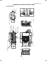
Page 17: ... 17 FILE NO SVM 13047 2 CONSTRUCTION VIEWS EXTERNAL VIEWS 2 1 RAV SP56 ATP ...

Page 18: ... 18 FILE NO SVM 13047 2 2 RAV SP80 ATP ...

Page 19: ... RAV TWP50E2 Simultaneous Twin Inner diameter Ø C Inner diameter Ø D Inner diameter Ø D A B Model RBC TWP30E2 Liquid side Gas side TWP50E2 Liquid side Gas side A B C D 36 14 Ø9 5 Ø6 4 43 23 Ø15 9 Ø12 7 34 14 Ø9 5 Ø9 5 44 21 Ø15 9 Ø15 9 ...

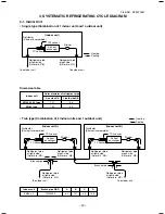
Page 20: ... sensor To outdoor unit Branch pipe Air heat exchanger Heating Cooling Indoor unit Refrigerant pipe at liquid side Outer dia ØB Refrigerant pipe at gas side Outer dia ØA Distributor Strainer incorporated Strainer Heating Cooling TCJ sensor TC sensor Air heat exchanger To outdoor unit To outdoor unit s Single type Combination of 1 indoor unit and 1 outdoor unit s Twin type Combination of 2 indoor u...

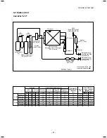
Page 21: ...Valve CAM B30YGTF 2 Standard Cooling Overload Low load Standard Heating Overload Low load Pressure MPa kg cm g Pd Ps Pd Ps 2 87 1 00 29 3 10 2 3 57 1 10 36 4 11 2 1 71 0 76 17 4 7 8 2 26 0 68 23 1 6 9 3 25 1 14 33 2 11 6 2 00 0 25 20 4 2 6 Pipe surface temperature C Discharge Suction Indoor heat Outdoor heat exchanger exchanger TD TS TC TE 72 16 13 42 88 20 19 52 45 12 7 13 66 6 37 3 78 20 53 16 7...

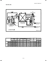
Page 22: ...r Muffler PMV Pulse Motor Valve CAM B30YGTF 2 Standard Cooling Overload Low load Standard Heating Overload Low load Pressure MPa kg cm g Pd Ps Pd Ps 2 79 0 89 27 3 8 7 3 53 1 07 34 6 10 5 1 71 0 72 16 8 7 1 2 65 0 68 26 0 6 7 3 20 1 11 31 4 10 9 2 33 0 21 22 8 2 1 Pipe surface temperature C Discharge Suction Indoor heat Outdoor heat exchanger exchanger TD TS TC TE 70 13 11 39 81 17 14 48 42 7 3 18...

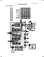
Page 23: ... 23 FILE NO SVM 13047 1 4 WIRING DIAGRAM 4 1 RAV SP56 ATP ...

Page 24: ... 24 FILE NO SVM 13047 4 2 RAV SP80 ATP ...

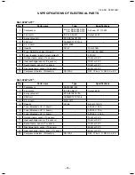
Page 25: ...harge temp sensor Td sensor 50 kΩ at 25 C 13 Compressor thermo Protection CS 12AL OFF 125 4 C ON 90 5 C RAV SP80 ATP No Parts name Type Specifications 1 Compressor DA220A2F 22L 2 Fan motor ICF 280 A60 1 Output 60 W 3 4 way valve coil STF H01AP1874A 4 PMV coil CAM MD12TCTH 6 5 P C board MCC 1571 6 Reactor CH 56 5 8 mH 18 5 A 7 Fuse Mounted on P C board AC250 V 25 A 8 Fuse Mounted on P C board AC250...

Page 26: ...e abnormally high so that a rupture or personal injury may be caused 5 After completion of installation work check to make sure that there is no refrigeration gas leakage If the refrigerant gas leaks into the room coming into contact with fire in the fan driven heater space heater etc a poisonous gas may occur 6 When an air conditioning system charged with a large volume of refrigerant is installe...

Page 27: ...d be taken to ensure that water or dust does not enter the pipe interior that no other oil other than lubricating oils used in the installed air conditioner is used and that refrigerant does not leak When using lubricating oils in the piping processing use such lubricating oils whose water content has been removed When stored be sure to seal the container with an airtight cap or any other cover 1 ...

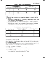
Page 28: ...5 0 to 0 5 0 to 0 5 0 to 0 5 Conventional flare tool R410A Clutch type Wing nut type 1 0 to 1 5 1 5 to 2 0 1 0 to 1 5 1 5 to 2 0 1 0 to 1 5 2 0 to 2 5 1 0 to 1 5 2 0 to 2 5 Conventional flare tool R22 Clutch type Wing nut type 0 5 to 1 0 1 0 to 1 5 0 5 to 1 0 1 0 to 1 5 0 5 to 1 0 1 5 to 2 0 0 5 to 1 0 1 5 to 2 0 Table 6 2 4 Flare and flare nut dimensions for R410A Table 6 2 5 Flare and flare nut ...

Page 29: ...strong the flare nut may crack and may be made non removable When choosing the tightening torque comply with values designated by manufacturers Table 6 2 6 shows reference values NOTE When applying oil to the flare surface be sure to use oil designated by the manufacturer If any other oil is used the lubricating oils may deteriorate and cause the compressor to burn out Table 6 2 6 Tightening torqu...

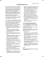
Page 30: ...mHg place the handle Low in the fully closed position and turn off the vacuum pump s power switch Keep the status as it is for 1 to 2 minutes and ensure that the compound gauge s pointer does not return Set the refrigerant cylinder to the electronic balance connect the connecting hose to the cylinder and the connecting port of the electronic balance and charge liquid refrigerant 1 Never charge ref...

Page 31: ...azing filler is an alloy mainly composed of silver and copper It is used to join iron copper or copper alloy and is relatively expensive though it excels in solder ability 2 Phosphor bronze brazing filler Phosphor bronze brazing filler is generally used to join copper or copper alloy 3 Low temperature brazing filler Low temperature brazing filler is generally called solder and is an alloy of tin a...

Page 32: ...eteriorates Therefore use a flux which does not contain chlorine 3 When adding water to the flux use water which does not contain chlorine e g distilled water or ion exchange water 4 Remove the flux after brazing 6 5 3 Brazing As brazing work requires sophisticated techniques experiences based upon a theoretical knowledge it must be performed by a person qualified In order to prevent the oxide fil...

Page 33: ... powder is observed the cause of trouble will occur 8 Installation and removal of the air conditioner are repeated with temporary installation by lease and etc 9 In case that type of the refrigerator oil of the existing air conditioner is other than the following oil Mineral oil Suniso Freol S MS Synthetic oil alkyl benzene HAB Barrel freeze ester series PVE only of ether series s Winding insulati...

Page 34: ... size to size for R410A Airtight test Vacuum dry Refrigerant charge Gas leak check In case that the gas pipe Ø19 mm is used for the outdoor unit of SP80 3 HP or higher Gas pipe size of our R410A model 3 is Ø15 9 mm Turn the existing pipe switch on the cycle control P C board of the outdoor unit to ON side At shipment from factory OFF ON for existing pipe Refer to the table below Be sure to set the...

Page 35: ...orresponds to any of the follow ing do not use it Install a new pipe instead s The pipe has been open disconnected from indoor unit or outdoor unit for a long period s The pipe has been connected to an outdoor unit that does not use refrigerant R22 R410A or R407C s The existing pipe must have a wall thickness equal to or larger than the following thickness s Never use any pipe with a wall thicknes...

Page 36: ...rmance In such case recover the refrigerant and replenish the refrigerant Restrictions for the amount of additional charging a The amount of refrigerant additionally charged shall not exceed 10 of that specified If the situation is not solved with such amount recover the refrigerant completely and charge the specified amount b In case of slow leakage upon installation and the pipe connection lengt...

Page 37: ...EMENT A sensor trouble may cause a liquid back flow or abnormal overheat resulting in excessive shortening of the compressor life In a case of trouble on the compressor be sure to check there is no error in the resistance value or the refrigerating cycle of each sensor after repair and then start the operation 2 Discharge temperature release control 1 When the discharge temperature did not fall or...

Page 38: ...FF Revolution frequency hold Operation with the maximum tap of each zone Operation with WF Normal fan control by TE sensor 1 tap 20 sec Down to the minimum revolution frequency of each zone TE C TD C 85 80 75 65 32 29 3 1 Cooling fan control SP56 The outdoor fan is controlled by TE sensor TO sensor and the operation frequency It is controlled by every 1 tap of DC fan control 15 taps Only for 60 se...

Page 39: ...THERMO OFF without error display The compressor restarts after approx 2 minutes 30 seconds and this intermittent operation is not abnormal In case that the status in item generates frequently stain on filter of the suction part of the indoor unit is considered Clean the filter and then restart the operation 4 Coil heating control 1 This control function heats the compressor by turning on the stopp...

Page 40: ...eration start in some cases the compressor does not stop to protect the compressor even if receiving the THERMO OFF signal from indoor However it is not abnormal status The operation continuance differs according to the operation status 2 When the operation stops by the remote controller the operation does not continue 6 Current release control No of revolutions of the compressor is controlled by ...

Page 41: ...hen the error count 8 was found determine an error and restart operation is not performed 4 For the error display contents confirm on the check code list 9 High pressure release control SP80 only 1 The operation frequency is controlled to restrain abnormal rising of high pressure by TL sensor in cooling operation and TC sensor in heating operation 2 When TL sensor in cooling operation or TC sensor...

Page 42: ...The minimum TE value and To value between 10 and 15 minutes after heating operation has started are stored in memory as TE0 and To0 respectively 0 10 15 29 35 91 min TE C 4 6 10 25 A zone A zone B zone B zone C zone C zone Start of heating operation D zone D zone A zone B zone C zone D zone o T l a m r o n b a n I o T l a m r o n n I When status TE0 TE To0 To 3 C When status TE0 TE 3 C s d n o c e...

Page 43: ...only 1 This control purposes to raise the operation frequency until 45Hz for 2 minutes in order to protect the compressor Prevention of oil accumulation in the refrigerating cycle when the status that the operation frequency is 45Hz or less has continued for 10 hours was calculated The operation frequency follows the normal indoor command after controlling 2 Although the compressor may stop by THE...

Page 44: ...er line Comp drive circuit Q200 to Q205 IGBT QTY 6P IC200 Drive IC QTY 1P L phase power supply lead Black N phase power supply lead White Serial lead Orange Reactor lead connector White CN300 Fan motor connector CN602 Outdoor temperature TO sensor connector CN806 Optional connector CN600 Heat exchange temperature TE sensor connector CN603 Suction temperature TS sensor connector CN601 Discharge tem...

Page 45: ...een Initial set SW SW802 Power circuit protective fuse F100 250V 3 15A plastic case Fan motor output CN300 White Compressor output terminals CN202 CN201 CN200 Electrolytic capacitors Reactor connecting connectors Power supply connecting lead wire P01 Red P02 White Lead wire for grounding P09 Black PMV connector CN710 White Inter unit wire connector CN04 White 4 way valve protective fuse F700 250V ...

Page 46: ...side low temperature operation control work in cooling operation s Is not defrost operation performed 4 ON OFF operation cannot be performed from remote controller s Is not the control operation performed from outside remote side s Is not automatic address being set up When the power is turned on at the first time or when indoor unit address setting is changed the operation cannot be performed for...

Page 47: ...remote controller s Is not forced operation performed s Is not the control operation performed from outside remote side s Is not automatic address being set up s Is not being carried out a test run by operation of the outdoor controller a Did you return the cabling to the initial positions b Are connecting cables between indoor unit and receiving unit correct 2 Troubleshooting procedure When the p...

Page 48: ... and indoor unit Receiving error Receiving unit Miswiring or wire connection error Sending error Communication stop between receiving unit and indoor unit Duplicated indoor unit No Setup error Duplicated master units of remote controller Communication error between CPUs on indoor unit P C board Wire connection error between indoor units Indoor power OFF Communication stop between indoor master and...

Page 49: ...sensor error Heat exchanger sensor TA error Discharge temp sensor TD error Temp sensor TE error Temp sensor TL error Temp sensor TO error Sensor error of outdoor unit 1 Temp sensor TS error Temp sensor TH error Temp sensor miswiring TE TS Indoor EEPROM error Outdoor EEPROM error Compressor break down Compressor lock Current detection circuit error Outdoor compressor system error 1 Case thermostat ...

Page 50: ...n Operation Timer Ready Simultaneous flash Operation Timer Ready Alternate flash Check code Cause of trouble occurrence During test run Disagreement of cool heat Automatic cool heat setting to automatic cool heat prohibited model or setting of heating to cooling only model ...

Page 51: ...ts Open Short of discharge temp sensor was detected Open Short of heat exchanger temp sensor was detected Miswiring between TE sensor and TS sensor Open Short of outside temp sensor was detected Open Short of heat exchanger temp sensor was detected Open Short of suction temp sensor was detected Open Short of heat sink temp sensor Board installed was detected Misconnection of outdoor heat exchanger...

Page 52: ... Detection Indoor Indoor Indoor Indoor Indoor Indoor Indoor Indoor Network adapter Network adapter Center Network adapter Center Network adapter Explanation of error contents Open Short of heat exchanger TCJ was detected Open Short of heat exchanger TC was detected Open Short of room temp TA was detected EEPROM error Other error may be detected If no error automatic address is repeated Indoor AC f...

Page 53: ...r is detected Displayed when error is detected Displayed when error is detected Displayed when error is detected Displayed when error is detected Displayed when error is detected Displayed when error is detected Displayed when error is detected Displayed when error is detected Displayed when error is detected Displayed when error is detected Displayed when error is detected Judgment and measures 1...

Page 54: ...by central controller side Status of air conditioner Stop Stop Automatic reset If center exists operation continues Stop Automatic reset If center exists operation continues Stop Sub unit continues operation Stop Automatic reset Continues By remote controller Continuation Stop According to each case Condition Displayed when error is detected Displayed when error is detected Displayed when error is...

Page 55: ...ror is detected Displayed when error is detected Displayed when error is detected Displayed when error is detected Displayed when error is detected Displayed when error is detected Displayed when error is detected Displayed when error is detected Displayed when error is detected Displayed when error is detected Displayed when error is detected Displayed when error is detected Displayed when error ...

Page 56: ...error is detected Displayed when error is detected Displayed when error is detected Judgment and measures 1 Check refrigerating cycle Gas leak 2 Trouble of electronic expansion valve 3 Check discharge temp sensor TD 1 Check case thermostat and connector 2 Check gas leak recharge 3 Check whether the service valve is fully opened 4 Check PMV Pulse Motor Valve 5 Check broken pipe 1 Check power supply...

Page 57: ...S YES NO YES NO 8 2 3 Diagnostic Procedure for Each Check Code Outdoor Unit 1 This section describes the diagnostic method for each check code displayed on the wired remote controller 2 When APPLICATION CONTROL KIT TCB PCOS1E2 sold separately is connected the error contents can be judged by LED on the APPLICATION CONTROL KIT In this case turn off both bit 1 and 2 of DIP switch 01 on the All purpos...

Page 58: ... value of TO sensor correct Correct connector Sensor error Replace Check outdoor P C board Defect Replace TE TS sensor Check PMV Defective Replace Is wiring connection correct Compressor lead P C board side Compressor side Reactor cord Power supply lead Is wiring connection correct Compressor lead P C board side Compressor side Reactor cord Power supply lead YES NO YES NO YES YES YES YES YES YES Y...

Page 59: ...prove the cause of overload Correct connector Sensor error Replace Check outdoor P C board Defect Replace Confirm power supply construction etc Check outdoor P C board Defect Replace YES YES YES YES NO YES NO YES NO NO NO YES NO YES NO NO Check code H03 APPLICATION CONTROL KIT LED display D01 D02 D03 D04 Red Yellow Yellow Yellow Check Countermeasures Part without special mention indicates a part o...

Page 60: ...sor Rare short etc Defective Replace Correct power line Correct wiring YES NO YES YES YES YES NO YES NO NO NO NO NO YES YES NO After pulling out the connector of the fan motor CN300 rotate its shaft by hands Can it rotate smoothly Is the fan motor coil resistance within the range described below Between red and white lead 18 to 30Ω Between white and black lead 18 to 30Ω Between black and red lead ...

Page 61: ...ntroller may differ from that of LED How to check LED display on outdoor P C board Dip switch setup s When turning on 1 only of SW803 the latest error is displayed As the memory is stored it can be confirmed even if the power supply is turned off once excluding outside temp sensor TO error s When the work finished or the outdoor temp sensor TO error was found turn off all of SW803 The error which ...

Page 62: ... Display 2 Display 1 Display 2 Display 1 Display 2 Display 1 Display 2 Display 1 Display 2 Display 1 Display 2 Check and troubleshooting Item without special mention Indicates part of outdoor unit Discharge temp sensor TD error s There is a possibility that it is one of the following errors Confirm LED on outdoor P C board to judge which error it is Heat exchanger temp sensor TE error Heat exchang...

Page 63: ...sistance value of TS sensor correct Is connection of CN602 correct Is resistance value of TO sensor correct Is connection of CN600 correct Is resistance value of TS sensor correct Is connection of CN601 correct Is resistance value of TE sensor correct YES YES YES YES YES NO NO NO NO NO Check code F08 F12 F13 F15 F31 Outdoor LED display Display 1 Display 2 Display 1 Display 2 Display 1 Display 2 Di...

Page 64: ...r lead Board side Compressor side Reactor lead Power supply lead Is wire connection correct Compressor lead Board side Compressor side Reactor lead Power supply lead Compressor lock Replace Check outdoor P C board Defect Replace Check TE TS sensors and PMV Defect Replace Check outdoor P C board Defect Replace Check outdoor P C board Defect Replace YES YES YES YES YES YES YES YES NO NO NO NO NO NO ...

Page 65: ...t packaged with the service P C board Is service valve fully opened Is PMV under correct conditions Is there gas leak Is there refrigerant shortage Are CN609 connection and case thermostat correct Short each pins of CN609 Can compressor operate YES YES NO YES YES NO NO YES NO NO Check code H04 L10 Outdoor LED display Display 1 Display 2 Display 1 Display 2 Check and troubleshooting Item without sp...

Page 66: ... is one of the following errors Confirm LED on outdoor P C board to judge which error it is Communication error between MCU Heat sing temp sensor TH error EEPROM error Unset model type Heat sink overheat error Gas leak detection 4 way valve inverse error Communication error between MCUs Heat sink temp sensor TH error Refer to F13 column EEPROM error Refer to F31 column Unset model type Refer to L1...

Page 67: ... P C board Defect Replace Is AC mains voltage correct 198 to 264V NO YES Check code P03 P04 P05 Outdoor LED display Display 1 Display 2 Display 1 Display 2 Display 1 Display 2 Display 1 Display 2 Display 1 Display 2 Check and troubleshooting Item without special mention Indicates part of outdoor unit Discharge temp error There is a possibility that it is one of the following errors Confirm LED on ...

Page 68: ...e crushed pipe Is service valve fully opened Is PMV under correct conditions Is there gas leak Is there refrigerant shortage Check temp sensor TD sensor CN603 TS sensor CN600 Does something block the ventilation around the heat sink Does something block air flow from the fan Apply radiation grease to objective parts Retightening of screws Be sure not to forget to attach insulating sheet between he...

Page 69: ... way valve reversal error Check method of outdoor P C board operation Self holding valve type 1 Set SW804 of Dip switch as the following figure and then push SW801 for approx 1 second to check exchange operation to cooling cycle heating cycle s Power is turned on for approx 10 seconds s In case of operating with the coil of 4 way valve connected to CN701 take interval over 1 minute before re opera...

Page 70: ...ge of refrigerant clogging of cycle broken pipe abnormal overload etc Defect Correct defect Check overcharge of refrigerant clogging of cycle broken pipe abnormal overload etc Defect Correct defect Eliminate interfering element Eliminate interfering element Heating season Heating operation Cooling season Cooling operation Is there anything which interfere heat exchange of outdoor unit s LOGGING OF...

Page 71: ... No code Outdoor LED display Display 1 Display 2 Display 1 Display 2 Display 1 Display 2 Display 1 Display 2 Check and troubleshooting Item without special mention Indicates part of outdoor unit Fan system error Single operation check for outdoor fan 1 Set Dip switch of SW804 as the following figure and then push SW801 for approx 1 second to check single operation of outdoor fan Use this method to...

Page 72: ... 00 10 25 7 764 7 990 8 218 5 013 5 192 5 375 3 312 3 451 3 594 2 236 2 343 2 454 1 540 1 623 1 709 1 082 1 146 1 213 0 7740 0 8237 0 8761 0 5634 0 6023 0 6434 Temperature C 0 10 20 25 30 40 50 60 70 80 90 100 Resistance value kΩ Ω Ω Ω Ω Minimum value Standard value Maximum value 150 5 161 3 172 7 92 76 99 05 105 6 58 61 62 36 66 26 47 01 49 93 52 97 37 93 40 22 42 59 25 12 26 55 28 03 17 00 17 92...

Page 73: ...7 Ω White Black Black Red Under 20 C Red White Black 3 Compressor Model DA220A2F 22L Measure the resistance value of each winding by using the tester Position Resistance value Red White 0 606 Ω White Black Black Red Under 20 C Red White Black 4 Fan motor Model ICF 140 43 4R Measure the resistance value of each winding by using the tester Position Resistance value Red White 21 00 1 05 Ω White Black...

Page 74: ... unit and then turn off the power supply NOTE The electric portion of the refrigerant recovery SW on the sub board is electrified therefore be careful to an electric shock SP80 1 Set the mode of the indoor unit to fan mode 2 Set all DIP switch SW804 to OFF Initial status and then push the button switch SW801 for approx 1 second The cooling operation starts During this time D805 Green LED flashes T...

Page 75: ...case the upper limit value of static pressure for duct is 5Pa or less on 25 C degrees and please use straight duct In this case the outdoor noise level may increase Turn the switch to ON when Ø19 1 is used for the existing pipe In this case the heating capacity may lower according to outside temp and indoor temp in heating operation Turn the switch to ON when using the power save function The cont...

Page 76: ...s Orange LED Green LED Yellow LED Green LED Operation contents Indoor Outdoor communication Serial communication signal display Receive signal from indoor signal Indoor Outdoor communication Serial communication signal display Send signal from outdoor signal Error display When all SW803 are OFF or when any of D800 to D804 goes on LED displays that the outdoor controller detects an error When statu...

Page 77: ...or Latest error including present After error status was cleared the error which generated before can be confirmed by this setting Reconfirmation is available even if power supply was turned off once s If an error generates at present the same contents as those of error which is generating at present are displayed s Only error of TO sensor is not displayed by this setting Confirm it by setting of ...

Page 78: ...2 3 4 1 As the error code displayed on the wired remote controller may differ according to type of indoor model multiple codes are described Display 1 Initial display Display 2 SW800 operation Error contents Normal Discharge temp sensor TD error Heat exchanger temp sensor TE error Heat exchanger temp sensor TL error Outside temp sensor TO error Suction temp sensor TS error Heat sink temp sensor TH...

Page 79: ...o 69 70 to 74 75 to 79 80 to 84 85 to 89 90 to 94 95 to 99 100 to 104 105 to 109 110 to 114 115 to 119 Over 120 Sensor error unconnected Current A 0 to 0 9 1 to 1 9 2 to 2 9 3 to 3 9 4 to 4 9 5 to 5 9 6 to 6 9 7 to 7 9 8 to 8 9 9 to 9 9 10 to 10 9 11 to 11 9 12 to 12 9 13 to 13 9 14 to 14 9 15 to 15 9 16 to 16 9 17 to 17 9 18 to 18 9 19 to 19 9 20 to 20 9 21 to 21 9 22 to 22 9 23 to 23 9 24 to 24 ...

Page 80: ... SW804 ON 2 3 4 1 SW804 ON 2 3 4 1 SW804 ON 2 3 4 1 SW804 ON 2 3 4 1 SW804 ON 2 3 4 1 SW804 ON 2 3 4 1 SW804 ON 2 3 4 1 SW804 ON 2 3 4 1 SW804 Operation when pushdown button switch SW801 is pushed Refrigerant recovery operation The outdoor unit performs cooling operation The indoor unit does not work by this operation alone Therefore operate the fan beforehand Refer 9 1 Refrigerant Recovery Contro...

Page 81: ... relay RY700 CN701 between 1 and 4 Voltage Approx 198 to 380V This function works for 10 seconds and then is OFF SV valve relay operation For RY702 CN702 check Turn on SV valve relay RY702 When pushing SW801 again or when 2 minutes elapsed the operation returns to the normal control For RAV SP1104AT E to RAV SP1404AT E the part is not mounted so do not operate Heater output relay operation For che...

Page 82: ...net ST1T Ø4 8L 5 pcs s After taking off screws remove the upper cabinet pulling it upward 2 Attachment 1 Attach the waterproof cover CAUTION Be sure to attach a waterproof cover If it is not attached there is a possibility that water enters inside of the outdoor unit 2 Attach the upper cabinet ST1T Ø4 8L 5 pcs s Hook the rear side of the upper cabinet to claw of the rear cabinet and then put it on...

Page 83: ...n front cabinet and bottom slab ST1T Ø4 8 3 pcs 5 Remove the screw between front cabinet and motor base ST1T Ø4 8 2 pcs s EFT SIDE OF FRONT PANEL IS INSERTED INTO side cabinet left Remove by pulling the upper part 2 How to install 1 Insert front panel s hook into side cabinet left 2 Insert side cabinet left s hook into front cabinet s corner hole 3 Insert the removed screws to their positions Hook...

Page 84: ...as CAU TION HIGH VOLTAGE electrolytic capaci tor 500μF of P C board WARNING The electrolytic capacitor may not normally discharge according to error contents and the voltage may remain Therefore be sure to discharge the capacitor WARNING For discharging never use a screwdriver and others for short circuiting between and electrodes As the electrolytic capacitor is one with a large capacity it is ve...

Page 85: ...nnector by holding the lead wire but by holding the connector s ONNECTOR ONNECTION TO COMPRESSOR 3P Relay connector white Warning 1 Reactor 2P Relay connector white Outdoor fan 3P white Warning 1 4 directional valve 3P yellow Warning 1 PMV coil 6P white Warning 1 TD sensor 3P white TS sensor 3P white Warning 1 TE sensor 2P white Warning 1 TO sensor 2P white ASE THERMO 0 LUE Warning 1 Warning 1 Ple...

Page 86: ...housing part s lock before removing connectors 3 Remove inverter box metal plate 4 Remove control board frame from PC board base Remove while heat sink is still attached to control board frame Warning 2 Remove PC board base s hook 4 places hold heat sink pull up 5 Take off 2 screws that connect heat sink and control board frame 6 Install new control board frame Warning 3 When install new control b...

Page 87: ...1 of 1 and 2 2 Take off the flange nut fixing the fan motor and the propeller s Turning it clockwise the flange nut can be loosened To tighten the flange nut turn counterclockwise 3 Remove the propeller fan 4 Disconnect the connector for fan motor from the inverter 5 Take off the fixing screws 3 pcs holding by hands so that the fan motor does not fall NOTE Tighten the flange nut with torque 4 9Nm ...

Page 88: ...fixing screws of the bottom plate and heat exchanger ST1T Ø4 8L 8 Take off the fixing screws of the valve clamping plate to the bottom plate ST1T Ø4 8L 2 pcs 9 Pull upward he refrigerating cycle 10 Take off nut fixing the compressor to the bottom place CAUTION When reconnecting the lead wires to the compressor terminals after replacement of the compressor be sure to caulk the Faston terminal witho...

Page 89: ...rm works of items 1 of 1 and 2 2 Remove the front cabinet and put it down so that fan guard side directs downward CAUTION Perform works on a corrugated cardboard cloth etc to prevent flaw on the product 3 Remove the hooking claws by pushing with minus screwdriver along with the arrow mark in the right figure and remove the fan guard 2 Attachment 1 Insert claws of the fan guard in the hole of the f...

Page 90: ...10 5 pcs 2 Attachment 1 Attach the top plate Hexagonal screw Ø4 10 5 pcs In this time insert the fin guard of rear side between the top plate and the heat exchanger Rear side 2 Connect the power supply wire and the indoor outdoor connecting wire to the terminal and fix it with cord clamp CAUTION Using bundling band on the market be sure to fix the power wire and indoor outdoor connecting wire alon...

Page 91: ...Ø4 8 2 pcs 5 Remove screws of the discharge port cabinet and the heat exchanger ST1T Ø4 8 1 pc 6 Remove screws of the discharge port cabinet and the fin guard Hexagonal screw Ø4 10 2 pcs Remarks 1 Carry out work of 1 of 1 2 Remove screws which fix the inverter assembly and the side cabinet ST1T Ø4 8 2 pcs 3 Remove screws of the side cabinet and the valve fixing plate ST1T Ø4 8 2 pcs 4 Remove screw...

Page 92: ...ew with collar for fixing element Ø3 16 7 pcs Pan S tight screw for fixing P C board Ø3 20 1 pc 6 Remove the control P C board Supporter 5 positions NOTE It is difficult to take out it because of radiator grease for heat sink 7 Mount a new control P C board NOTE Do not forget to attach the aluminum plate Q201 and the insulating sheet Q300 Applying a little of radiator grease at the rear surface of...

Page 93: ...he removed bundling band with the bundling band on the market Be careful that the fan motor lead does not come to contact with the reactor body Remarks Reactor relay connector Connected to lead wire White at P C board side Reactor relay connector Connected to lead wire Charcoal gray at P C board side Fan motor lead Bundling band Compressor lead reactor lead Upper reactor Connected to reactor relay...

Page 94: ...length on the fan motor lead fixing rubber so that the fan motor lead does not slacken in order not to put the fan motor lead into contact with the propeller fan Attach the fan motor lead fixing rubber to the partition plate so that projection directs to the refrigerating cycle side Be sure that the rector body does not come to contact with the fan motor lead Be sure to bind the removed bundling b...

Page 95: ...emove terminal cover from the compressor and then remove the compressor lead and also the compressor case thermo 8 Remove TD sensor fixed to the discharge pipe 9 Remove the compressor lead Leave the ferrite core attached to the electric parts box as it is Control P C board U CN200 Red V CN201 White W CN202 Black Tightening torque 1 47 0 1Nsm Remarks Compressor lead Ferrite core Compressor lead Fer...

Page 96: ... the moment when wax melted so take sufficient care CAUTION Note so that the flame does not catch the 4 way valve and PMV An operation may become an error 11 Pull off the discharge pipe and the suction pipe of the refrigerating cycle upward 12 Remove the compressor bolts which fix the compressor to the bottom plate 3 pcs 13 Pull out the compressor toward you X CAUTIONX The weight of the compressor...

Page 97: ...E TD TS sensor PMV coil lead wire Set each sensor so that it does not come to contact with the discharge pipe PMV coil lead Pass the soundproof plate inner winding through between compressor and discharge pipe suction pipe and then put it on the other side at this position No 6 Part name Compressor Compressor lead Continued Procedure 2 Mounting of compressor 1 Mount the compressor in the reverse p...

Page 98: ...breaker Turn on 1 and 3 of DIP SW804 on the control P C board of the outdoor unit Keep pushing SW801 on the control P C board of the outdoor unit for 1 second or more After pushing SW801 for 1 second or more turn off the leakage breaker within 2 minutes 4 Refrigerant charging 1 Add the quantity of refrigerant specified by the pipe length into the charge port of the valve Remarks 1 Detachment 1 Car...

Page 99: ... Remove the discharge port cabinet and then put on it so that the fan guard side directs downward 3 Remove the hooking claws 8 positions of the fan guard 2 Attachment 1 Push the hooking claws 8 positions with hands from the front side to fix the claws CAUTIONX Check that all the hooking claws are fixed at the specified positions Remarks Bell mouth Discharge port cabinet Fan guard Hooking claw ...

Page 100: ... 100 FILE NO SVM 13047 1 11 1 RAV SP564ATP A 11 EXPLODED VIEWS AND PARTS LIST ...

Page 101: ...PACKED 12 7 DIA 1 017 43T46358 VALVE PACKED 6 35 DIA 1 018 43T43471 CONDENSER ASSEMBLY 1 020 43T21375 FAN MOTOR 1 021 43T20319 PROPELLER FAN 1 022 43T19329 FAN GUARD 1 023 43T19331 FIN GUARD 1 024 43T58306 REACTOR 2 025 43T60439 COMPRESSOR LEAD ASSEMBLY 1 026 43T54319 THERMOSTAT BIMETAL 1 027 43T50307 HOLDER THERMOSTAT 1 028 43T63317 HOLDER SENSOR 1 029 43T63323 HOLDER SENSOR 1 030 43T63318 HOLDER...

Page 102: ... 102 FILE NO SVM 13047 TD TS TE TO 705 708 710 704 702 701 703 711 707 712 706 Inverter assembly ...

Page 103: ...r TS 1 703 43T60430 Sensor TO 1 704 43T60431 Sensor TD 1 705 43T62313 Base Plate PC 1 706 43T60423 ASM SERV Terminal block 6P 20A 1 707 43T6V363 P C board Ass y SW MCC 1530 1 708 43T6V362 P C board Ass y MCC 5009 1 710 43T60425 Fuse holder 15A 250V 1 711 43T60426 Fuse 6 3A 250VAC 1 712 43T60422 Reactor CH 76 TM1 1 ...

Page 104: ... 104 FILE NO SVM 13047 11 2 RAV SP804ATP A ...

Page 105: ... COIL PMV 1 018 43T46381 VALVE BALL 15 88 DIA 1 019 43T46380 VALVE PACKED 9 52 DIA 1 020 43T43472 CONDENSER ASSEMBLY 1 022 43T47372 STRAINER 25 4 DIA 1 023 43T47373 STRAINER 12 7 DIA 1 024 43T21429 FAN MOTOR 1 025 43T20329 PROPELLER FAN 1 026 43T19343 FAN GUARD 1 027 43T22313 BELLMOUTH 1 028 43T19345 FIN GUARD 1 029 43T71302 HANDLE 2 030 43T60421 COMPRESSOR LEAD ASSEMBLY 1 031 43T54319 THERMOSTAT ...

Page 106: ... 106 FILE NO SVM 13047 Inverter assembly 1 2 3 705 709 710 711 707 704 706 703 701 708 702 712 713 ...

Page 107: ... y Ø4 2 704 43T58307 Reactor CH 56 2Z T 2 705 43T60427 ASM SERV Terminal block 3P 20A 1 706 43T60424 ASM SERV Terminal block 3P 60A 1 707 43T60413 Fuse 10A 250V AC 1 708 43T63335 Holder Sensor TO 1 709 43T61315 Spacer Bush 1 710 43T61316 Spacer Collar 1 711 43T6V361 P C board Ass y MCC 1571 1 712 43T63323 Holder Sensor TS 1 713 43T63317 Holder Sensor TD 1 ...

Page 108: ...procedure so that if the refrigerant accidentally leaks out its concentration does not reach the limit and in the event of an emergency measures can be made before injury can occur In a room where the concentration may exceed the limit create an opening with adjacent rooms or install mechanical ventilation combined with a gas leak detection device The concentration is as given below Total amount o...

Page 109: ......

Reviews: