– 3
8
–
FILE NO. SVM-13047
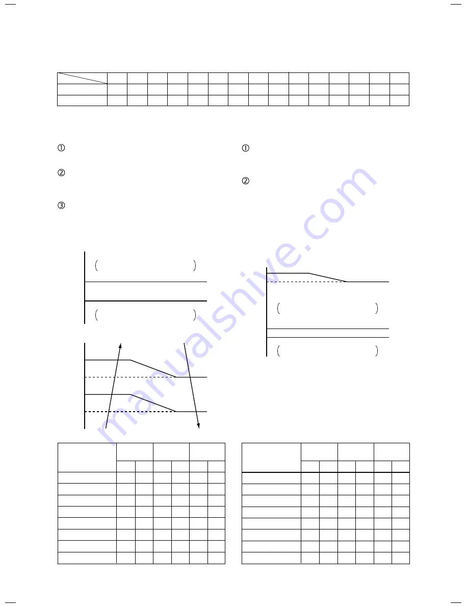
3. Outdoor fan control
Revolution frequency allocation of fan taps [rpm]
WF tap
+1 tap / 20 sec
Up to the maximum
revolution frequency of each zone
Revolution frequency hold
–1 tap / 20 sec
Down to the minimum
revolution frequency of each zone
TL [˚C]
58
55
38
35
Temp. range
38°C
≤
TO
29°C
≤
TO < 38°C
15°C
≤
TO < 29°C
5°C
≤
TO < 15°C
0°C
≤
TO < 5°C
–4°C
≤
TO < 0°C
TO < –4°C
TO error
20 Hz
20Hz
45Hz
or lower
to 45Hz
or higher
Min. Max. Min. Max. Min. Max.
W6
WC
W8
WE
WA
WE
W5
WB
W7
WD
W9
WD
W4
W8
W6
WA
W8
WC
W3
W6
W5
W8
W7
WA
W2
W4
W4
W6
W5
W8
W2
W3
W3
W5
W4
W6
OFF
OFF
OFF
W2
OFF
W3
OFF
WC
OFF
WE
OFF
WE
<SP80>
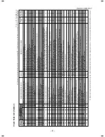
The outdoor fan is controlled by TL sensor, TO
sensor and the operation frequency.
The outdoor fan is controlled by every 1 tap of DC
fan control (15 taps).
Only for 60 seconds after the operation has
started, the maximum fan tap corresponding to the
zone in the following table is fixed and then the fan
is controlled by temperature of TL sensor.
+1 tap / 20 sec
Up to the maximum
revolution frequency of each zone
∗
Operation with W1 in case of fan-OFF
Revolution frequency hold
Operation with
the maximum tap
of each zone
Operation
with WF
Normal fan control
by TE sensor
–1 tap / 20 sec
Down to the minimum
revolution frequency of each zone
TE [˚C]
TD [˚C]
85
80
75
65
32
29
3-1) Cooling fan control
<SP56>
The outdoor fan is controlled by TE sensor, TO
sensor and the operation frequency. It is controlled
by every 1 tap of DC fan control (15 taps).
Only for 60 seconds after start-up of operation, it is
fixed by the maximum fan tap corresponded to the
zone in the following table, and then the fan is
controlled by temperature of TE sensor.
When temperature of TD sensor became high
sufficiently, it is controlled so that the fan revolution
frequency will become higher ignoring TE sensor
temperature.
SP56
SP80
W1
W2
W3
W4
W5
W6
W7
W8
W9
WA
WB
WC
WD
WE
WF
200
250
300
400
480
500
520
560
640
670
700
750
800
880
980
200
230
260
300
340
380
420
460
520
570
600
630
670
710
740
Temp. range
38°C
≤
TO
28°C
≤
TO < 38°C
15°C
≤
TO < 28°C
5.5°C
≤
TO < 15°C
0°C
≤
TO < 5.5°C
–5°C
≤
TO < 0°C
TO < –5°C
TO error
20 Hz
20Hz
45Hz
or lower
to 45Hz
or higher
Min. Max. Min. Max. Min. Max.
W6
WB
W7
WE
W9
WF
W5
WA
W6
WD
W8
WE
W3
W7
W4
W9
W6
WB
W2
W5
W3
W7
W5
W9
W1
W3
W2
W5
W3
W7
W1
W2
W1
W3
W2
W4
OFF
OFF
OFF
OFF
W1
W3
W1
WB
W1
WE
W1
WF
<SP56>
<SP80>
SVM-12085_001-050.indd 39
SVM-12085_001-050.indd 39
12/06/12 11:06 AM
12/06/12 11:06 AM
Summary of Contents for RAV-SP564ATP-A
Page 17: ... 17 FILE NO SVM 13047 2 CONSTRUCTION VIEWS EXTERNAL VIEWS 2 1 RAV SP56 ATP ...
Page 18: ... 18 FILE NO SVM 13047 2 2 RAV SP80 ATP ...
Page 23: ... 23 FILE NO SVM 13047 1 4 WIRING DIAGRAM 4 1 RAV SP56 ATP ...
Page 24: ... 24 FILE NO SVM 13047 4 2 RAV SP80 ATP ...
Page 100: ... 100 FILE NO SVM 13047 1 11 1 RAV SP564ATP A 11 EXPLODED VIEWS AND PARTS LIST ...
Page 104: ... 104 FILE NO SVM 13047 11 2 RAV SP804ATP A ...
Page 109: ......


