- EN -
INSTALLATION MANUAL
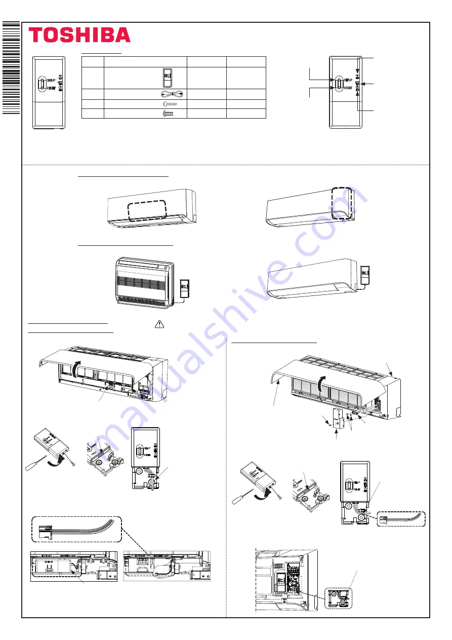
Wireless adapter
Accessory part.
No.
Part Name
RB-N105S-G
RB-N106S-G
1
Wireless adapter
TYPE B
1
1
2
Connection cable
-
1
3
SCREW : M4X25
*2
*2
4
SCREW : M4X12
*1
*1
*The number of parts may differ by model.
TYPE B
SETUP
button
Initial connection
to Wi-Fi router
WIRELESS LED
Show during A/C add
step and sending
signal to A/C
LINK LED
Show during
connecting process
POWER LED
Show for
Power On
RESET
button
For system reset
TYPE B
“The Wireless adapter must be installed, maintained, repaired and removed by a quali
fi
ed
installer or quali
fi
ed service person.”
1120490206
Installation position (Inside AC unit)
High - Wall type A
High - Wall type B
Installation position (Outside AC unit)
Console chassis
High - Wall type C
TYPE B
TYPE B
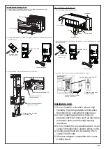
Caution : Turn off power supply before installation
1. Open air inlet grille and cover for controller.
2. Open Wireless adapter for connect terminal.
2. Open Wireless adapter for connect terminal.
3. Open cover place the controller and connect communication cable from AC and
close cover.
3. Place Wireless adapter to
fi
xing position and connect communication cable from
AC and close cover.
1. Open air inlet grille and terminal cover.
Cover for controller
Cover of adapter no need
fi
x screw
Fix by screw
Wire out position
TYPE B
Connect terminal
Cover of adapter
no need
fi
x screw
Communication cable
Communication
cable
Fix by screw
Wire out position
Connect terminal
High - Wall type B (Inside AC unit)
How to install Wireless adapter.
High - Wall type A (Inside AC unit)
Remove screw
remove cover
Remove screw
remove cover
TYPE B
Front panel
Cord clamp
Screws
Terminal cover
Air inlet grille
Screw


