background image

Wireless Remote Controller Kit

Owner’s Manual

– 5 –

„

Display section

All inticators are shown in the right and the lower figures for the 
explanation.
Only selected contents are display in actual operation.
• When turning on the leak breaker at the first time, [

SET DATA

flashes on the display part of the remote controller. 
While this display is flashing, the model is being automatically 
confirmed. 
Accordingly, wait for a while after [

SET DATA

] display has 

disappeared, and then use the remote controller.

1

Transmitting indication

Displayed while operating the switches of the 
remote controller.

2

Operation mode

The selected operation mode is displayed.

3

Fan speed display

The selected fan speed is displayed.

4

Filter display

, reminder to clean the air filter.

5

CHECK display

Displayed while the protective device works 
or a trouble occurs.

6

Set up temperature display

The selected set point is displayed.

7

Louver position display

Displays louver position.

8

Swing display

Displayed during up/down movement of the 
louver.

9

Timer display

Time of the timer is displayed.
(When a malfunction occurs, an error code is 
displayed.)

10

Timer mode display

Displays the timer mode.

ADR

SENSOR

ADR

ACL

Display 
section

Operation 
section

ADR

1

2

3

4

5

6
7

2

10

8

(AUTO)
(HIGH)
(MED.)
(LOW)

5-EN

Summary of Contents for RBC-AX23UW-E

Page 1: ...Español Manual do utilizador Kit do Controlador Remoto Sem Fios 71 Português Gebruiksaanwijzing Pakket met draadloze afstandsbediening 85 Nederlands α α υ υ 99 ǼȜȜȘȞȚțȐ 113 Ɋɭɫɫɤɢɣ Kullaným Kýlavuzu Kablosuz Uzaktan Kumanda Kiti 127 Türkçe 用户手册 无线遥控器套件 141 中文 Wireless Remote Controller Kit Model name For 2 way Air Discharge Cassette Type RBC AX23UW W E Generic model name Wireless remote controller...

Page 2: ...10 8 Handle the Remote Controller 11 9 Notes on Proper Use 11 10 Address Setting 12 11 Emergency Operation 13 12 Before Asking for Repair Work 14 Please read this Owner s Manual carefully for correct use before using your Wireless Remote Controller Kit Be sure to read Precautions for Safety After you read this manual please keep it with the Installation Manual of the air conditioner at accessible ...

Page 3: ...ntact with the dealer If the air conditioner is continuously operated with something abnormal it may cause machine failure electric shock or fire etc Warnings about Movement and Repair Do not repair any unit by yourself Whenever the air conditioner needs repair make sure to ask the dealer to do it If it is repaired imperfectly it may cause electric shock or fire etc When reinstalling the air condi...

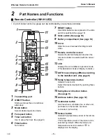
Page 4: ...nses the ambient temperature when the remote controller is selected with the sensor button 12 LCD Displays the air conditioner operation mode This illustration shows all display contents 13 AUTO louver display differs according to the installed unit See page 9 14 Setup temperature button Adjusts the set point Select the desired set point by pushing these buttons 15 Swing louver direction button Se...

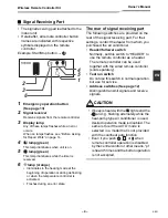
Page 5: ...tate The rear of signal receiving part The following switches are provided on the rear of the signal receiving part For their settings contact the dealer from whom you purchased the air conditioner Header follower switch Normally set this switch to HEADER to use the remote controller as a header The remote controller can be used together with the wired remote controller sold separately Test run sw...

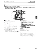
Page 6: ... while operating the switches of the remote controller 2 Operation mode The selected operation mode is displayed 3 Fan speed display The selected fan speed is displayed 4 Filter display reminder to clean the air filter 5 CHECK display Displayed while the protective device works or a trouble occurs 6 Set up temperature display The selected set point is displayed 7 Louver position display Displays l...

Page 7: ... 5 Setup temperature button Adjusts the set point Select the desired set point by pushing or 6 ON OFF button When the button is pushed the operation starts and it stops by pushing the button again When the operation has stopped the operation lamp and all the displays disappear 7 Filter button This function is not available OPTION Remote controller sensor Usually the temperature sensor of the indoo...

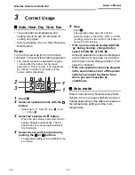
Page 8: ... fan speed does not change automatically in the Fan mode 4 Select the set point temperature by pushing the or buttons Temperature setting is not available for the Fan mode 5 Stop Push The operation lamp goes off and the operation stops In the COOL DRY or AUTO cooling mode the fan runs for 10 minutes or more for self cleaning If the room is not well heated with FAN during heating change the fan spe...

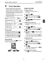
Page 9: ...lay 2 Set the time to 0 5 with TIME or 3 Push and the time stop flashing Setting repeat OFF timer Example To stop operation in every 2 5 hours 1 Push Timer twice and the time flash on the display 2 Set the time to 2 5 with TIME or 3 Push and the time stop flashing The OFF timer is activated and the operation stops in 2 5 hours When you push again to restart the operation it stops in 2 5 hours Sett...

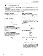
Page 10: ...layed and the louvers swing automatically In COOL DRY operation Direct the louver horizontally Otherwise dew drop may form around the discharge port and drop from the unit Stop swing operation Push at a desired position while the louver is swinging When is pushed the louver direction can be set again from the highest position In COOL DRY mode the louver does not stop as it directs downward If stop...

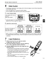
Page 11: ...over 2 Insert two AAA alkaline batteries correctly matching the and polarities with the indication 3 Push the RESET button with a fine tipped tool and attach the cover Replace batteries when the display on the remote controller has become dim or when signals from the remote controller cannot be received at the normal distance from the signal receiving part Alkaline batteries should be replaced onc...

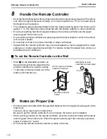
Page 12: ...om equipped with a rapid start type or inverter type fluorescent light For details contact the dealer from whom you purchased the air conditioner To set the Remote Controller on the Wall Push at the installation position on the wall to check that the signal from the remote controller is received correctly To take the remote controller out of the holder pull it toward you 9 Notes on Proper Use Put ...

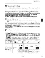
Page 13: ... controller is enabled regardless of the address switch setting in the signal receiving part Transmit signals while pointing the remote controller at the signal receiving part of the indoor unit to be controlled Matching Addresses Address setting on the remote controller 1 Push for at least 4 seconds Address lights up on the display and the current address flashes 2 Each time you push addresses ch...

Page 14: ... out of order The remote controller has been lost 1 Start Push emergency operation When the emergency operation is started at a room temperature of 24 C or more the air conditioner enters the cooling mode When the emergency operation is started at a room temperature below 24 C the air conditioner enters the heating mode 2 Stop Push emergency operation once again CAUTION The test run switch in the ...

Page 15: ...mer operation See page 8 The batteries of the remote controller have been exhausted Replace the batteries See page 10 The LEDs on the signal receiving part are not in normal state or operation mode is not correct Change the operation mode See page 4 Auto or Heat is displayed on the display though the air conditioner is cool only type Change the slide switch setting of the remote controller See pag...

Page 16: ...EH72394301 ...
Reviews: