‒
2
‒
Remote controller address (A-B selection) setting
• When two or more wireless receiver are installed in a room, a unique address can be
set for each wireless receiver to prevent interference.
• Address (A-B selection) must be changed on wireless remote controller.
Test run (Forced cooling operation)
Requirement
• Finish the forced cooling operation in a short time because it applies excessive
strength to the air conditioner.
How to perform forced cooling operation
1.
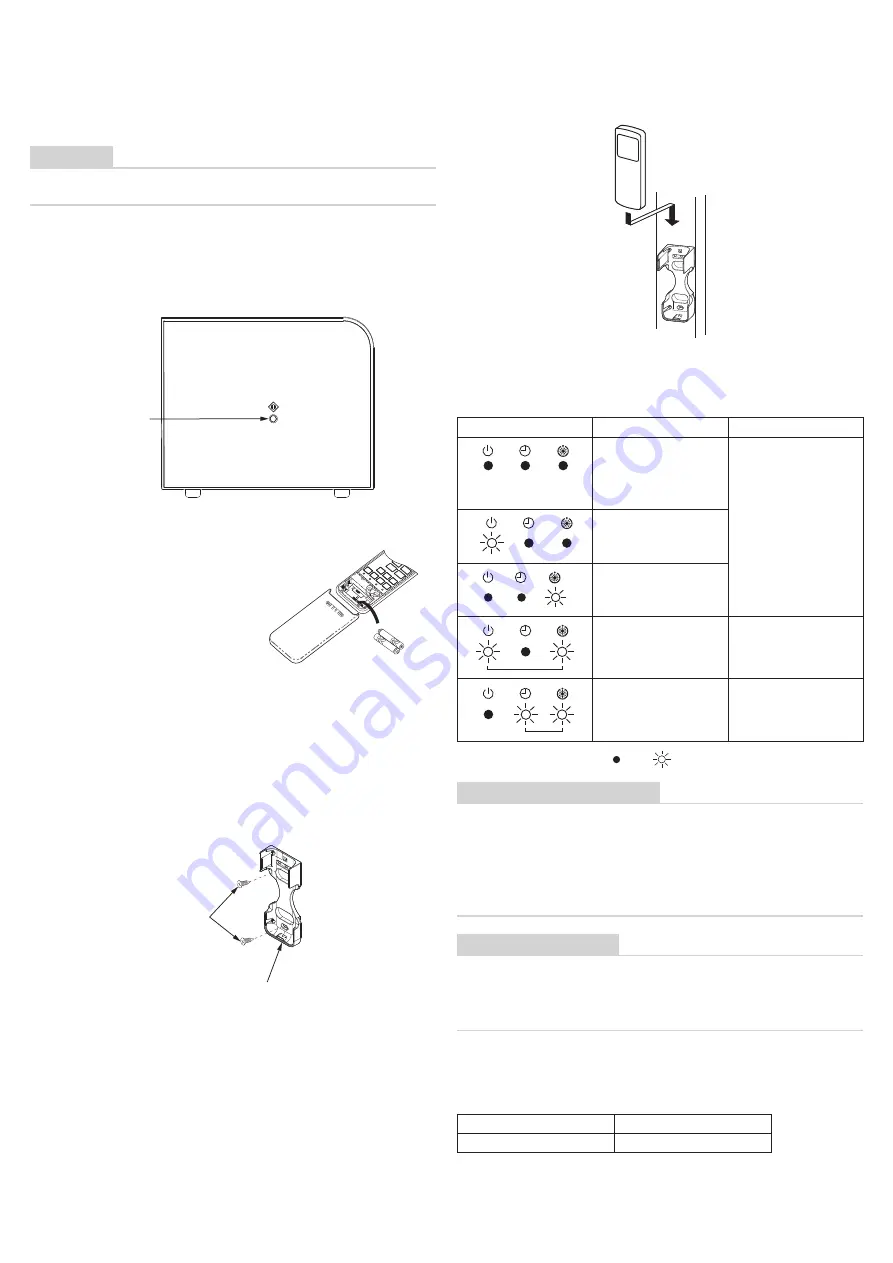
When TEMPORARY button is pushed for 10 seconds or more, “Pi!” sound is heard
and the operation changes to a forced cooling operation. After approx.
3 minutes, a cooling operation starts forcedly. Check cool air starts blowing.
If the operation does not start, check wiring again.
2.
To stop a test operation, push TEMPORARY button once again (Approx. 1 Sec.).
• Check wiring / piping of the indoor and outdoor unit in forced cooling operation.
TEMPORARY
button
Preparation and check before use
1. Loading Batteries
• Remove the battery cover.
• Insert 2 new batteries (R03 [AAA])
following the (+) and (-) positions.
2. Removing Batteries
• Remove the battery cover.
• Remove the 2 used batteries.
Batteries
• To replace the batteries, use two new batteries (R03 [AAA]).
• In normal use, the batteries will last about one year.
• Replace the batteries if there is no receiving beep from the indoor unit or when the air
conditioner cannot be operated using the remote controller.
• To avoid malfunctions by battery leakage, remove the batteries when not using the
remote controller for more than one month.
• Please dispose of the used batteries according to the local regulation.
Installing the remote controller holder
• Before you actually install the remote controller holder on a wall or pillar, check
whether the remote controller signals can be received by the indoor unit.
Flat head
wood screw
Remote control holder
Mounting and removing the remote controller
• To mount the remote controller hold it parallel to the remote controller holder and
push it in fully. To remove the remote controller slide the remote controller upwards
and out from the holder.
Self-diagnosis function and measures
• The following table shows a few examples. For details of indoor unit errors, refer to
the Installation Manual of the indoor unit.
LED
Possible cause
Measures
These LEDs do not light or
blink even if the remote
controller is operated.
- Power is not turned on.
- Incorrect connection between
signal receiving unit and
indoor unit
Check connections and
reconnect wires correctly, if
necessary.
Loose connection between
signal receiving unit and indoor
unit
Incorrect or loose connection
between indoor unit and
outdoor unit
The protective device of the
outdoor unit is activated.
Check the outdoor unit.
The protective device of the
indoor unit is activated.
Check the indoor unit.
LEDs on the signal receiving unit : OFF
: Blinking (at intervals of 0.5 seconds)
Notes on installing remote controller
• When using a wireless remote controller in the remote controller holder on a wall, turn
on a fluorescent light and operate the remote controller at the installation position.
Make sure that the air conditioner operates normally and then secure the remote
controller holder on the wall.
• When installing a remote controller that senses room temperature with the sensor,
avoid the following places.
• A place exposed to direct cool air, warm air or direct sunlight.
• A place subject to thermal effects.
Explanation to the customer
• After the installation work has been completed, execute a test run to check for normal
operation and then hand the customer the Owner’s Manual and Installation Manual of
the wireless remote controller kit.
• Explain how to use and maintain the wireless remote controller kit to the customer
according to the Owner’s Manual of the wireless remote controller kit.
List of separately available products that cannot be used with
the Wireless receiver kit.
The following separately available products cannot be used together with the
Wireless receiver kit.
Product name
Model
Occupancy sensor kit
TCB-SIR41UYP-E
1127699102


