background image

– 15 –

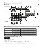
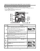
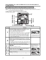
When you want to know position of the indoor unit using the address

To confirm the unit numbers in a group control

(Operation while the air conditioner stops)
The indoor unit numbers in a group control are successively displayed, and the corresponding indoor fan is turned
on.

Procedure

1

2

3

Description

Push

VENT

 + 

TEST

 buttons simultaneously for 4 seconds or more.

• UNIT No. 

 is displayed.

• The fans of all the indoor units in a group control are turned on.

Every pushing 

UNIT

LOUVER

 button, the indoor unit numbers in the

group control are successively displayed.

• The firstly displayed unit numbers indicates the address of the main

unit.

• Only fan of the selected indoor unit is turned on.

Push

TEST

 button to finish the procedure.

All the indoor units in group control stop.

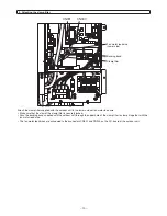
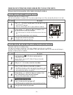
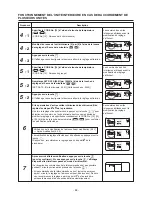
To confirm all the unit numbers from an arbitrary wired remote controller

(Operation while the air conditioner stops)
The indoor unit numbers and position in the same refrigerant cycle line can be confirmed.
An outdoor unit is selected, the indoor unit numbers in the same refrigerant cycle line are successively displayed,
and then its indoor unit fan is turned on.

Procedure

1

2

3

4

5

6

Description

Push the timer time 

 + 

TEST

 buttons simultaneously for

4 seconds or more.

Firstly, the line 1, item code 

 (Address Change) is displayed.

(Select outdoor unit.)

Using

UNIT

LOUVER

 + 

SWING/FIX

 buttons, select the line address.

Using

SET

 button, determine the selected line address.

• The indoor unit address, which is connected to the refrigerant cycle

line of the selected outdoor unit is displayed and the fan is turned
on and all display of indoor unit turned on.

Every pushing 

UNIT

LOUVER

 button, the indoor unit numbers in the

same refrigerant line are successively displayed.

• Only fan of the selected indoor unit operates.

To select another line address

Push

CL

 button to return to procedure 

2

.

• The indoor address of another line can be successively confirmed.

Push

TEST

 button to finish the procedure.

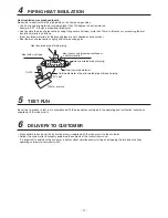
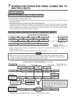
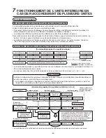
INDOOR UNIT OPERATION WHEN CONNECTED TO MULTIPLE UNITS

1

2

ON / OFF

FAN

TEMP.

TIME

MODE

SET

CL

FILTER
RESET TEST

TIMER SET

CODE No.

UNIT   No.

DATA

SET

R.C.

No.

ON / OFF

FAN

TEMP.

TIME

MODE

SET

CL

FILTER
RESET TEST

TIMER SET

CODE No.

UNIT   No.

DATA

SET

R.C.

No.

1

1, 6

2, 4

3

SAVE

SWING/FIX

VENT

UNIT LOUVER

SAVE

SWING/FIX

VENT

UNIT LOUVER

1, 3

5 2

Summary of Contents for RBC-TWP30E2

Page 1: ...e RBC TWP30E2 RBC TWP50E2 2 BRANCH PIPE KIT Installation manual ENGLISH 16 KIT DE TUYAU DE BRANCHEMENT Manuel d installation FRANÇAIS 30 AUSRÜSTUNG FÜR DIE ZWEIGLEITUNG Installations handbuch DEUTSCH 44 KIT DEI TUBI DI RACCORDO Manuale di installazione ITALIANO R32 or R410A ...

Page 2: ...on accumulation of highly concentrated refrigerant occurs cause an oxygen deficiency accident or a fire 4 For installation for indoor or outdoor unit please read the Installation Manual supplied with indoor or outdoor unit 5 Make sure to observe the cautions for each contents Be sure to follow the wiring or the setting procedure in the Installation Manual As for Precautions for safety please read ...

Page 3: ... 7 mm and 1 0 mm for diameter 15 9 mm Never use pipes of thin wall thickness such as 0 7 mm In parentheses are wall thickness Tolerance of pipe length and pipe head CAUTION Piping materials and sizes T A 0 6 1 T A 0 4 1 T A 0 1 1 V A R l e d o M Pipe side Gas side 0 1 9 5 1 Ø g n i p i p n i a M Branch piping Ø12 7 0 8 Ø15 9 1 0 Liquid side 8 0 5 9 Ø g n i p i p n i a M Branch piping Ø6 4 0 8 Ø9 5...

Page 4: ...become horizontal Fix the branch pipes onto a wall in a ceiling or onto a column Provide a straight pipe longer than 500 mm in length as the main piping of the branches For the complete information read the installation instructions for outdoor units of air conditioner Branch pipe Air Purging Horizontal Inclination Horizontal Inclination 500 mm or more Incorrect Incorrect ...

Page 5: ...eak detector manufactured specially for the HFC refrigerant R32 R410A R134a etc when testing R32 R410A The sensitivity of leak detectors for previous HCFC refrigerants such as R22 lowers to about 1 40 when used with HFC refrigerants and these detectors cannot be used Additional Refrigerant Amount Additional refrigerant amount kg Main piping additional refrigerant amount kg Branch piping additional...

Page 6: ...ndoor unit 1 Disconnect the read wire between remote controller terminal and CN41 RC connector on the P C board 2 Connect the Noise Filter between remote controller terminal and CN41 RC connector on the P C board 3 Bind this wire and main terminal wire by bind band 1 Install wires from the outdoor unit to the main unit as in usual wiring Wires 1 2 3 and ground wire 2 Install wires 1 2 and ground w...

Page 7: ...ic addressing It will require Max 10 minutes generally approx 3 minutes that outdoor unit starts operation after power was on Wiring Diagram Wiring Specification Outdoor unit indoor unit main unit e r i w d n u o r g e d u l c n I 4 s e r i w f o o N Wire diameter H07RN F or 245IEC66 1 5 mm2 or more Indoor unit main unit indoor unit sub unit 2 s e r i w f o o N Wire diameter H07RN F or 245IEC66 1 ...

Page 8: ...automatic addressing It will require Max 10 minutes generally approx 3 minutes that outdoor unit starts operation after power was on Wiring Diagram Wiring Specification Outdoor unit indoor unit main unit e r i w d n u o r g e d u l c n I 4 s e r i w f o o N Wire diameter H07RN F or 245IEC66 1 5 mm2 or more Indoor unit main unit indoor unit sub unit 2 s e r i w f o o N Wire diameter H07RN F or 245I...

Page 9: ...r outdoor connecting wires and through the supplied ferrite core and wind them making a single turn and then connect them to the terminals of the outdoor unit Connect the indoor outdoor connecting wire and the earth wire directly to the outdoor unit terminals 4 Attach the clamp filter gray supplied with the outdoor unit to the outdoor fan motor lead wire Attach the supplied clamp filter securely t...

Page 10: ...ocked Pass the banding band supplied with the outdoor unit through the upper hole of the clamp filter to clamp it together with the fan motor lead wire The fan motor lead wires are connected to the connectors CN301 and CN300 on the P C board of the outdoor unit 2 Attaching the clamp filter CN301 CN300 Fan motor lead wire Lower side Clamp filter Banding band ...

Page 11: ... certain to conduct a test run in accordance with the procedures contained in the operating and installation instructions supplied with the indoor units 6 DELIVERY TO CUSTOMER Make certain to hand over the instruction manual supplied with the indoor units to the customer Deliver the system after thoroughly explaining the contents of the instruction manual It is important to explain to the customer...

Page 12: ...guration that requires address change is the combined system where twin and triple system of multiple units are controlled by group control with single remote controller Group Control on Combined System For example t i n u r o o d t u O t i n u r o o d t u O t i n u r o o d t u O t i n u r o o d t u O t i n u r o o d t u O Indoor unit Remote controller After the power is turned on address setting ...

Page 13: ...roup control the indoor unit numbers that is displayed first becomes the main unit Every pushing UNIT LOUVER button the indoor unit numbers in the group control are successively displayed Select the indoor unit of which setting is to be changed At this time the fan of the selected indoor unit is turned on and LED indicator on the indoor unit will light up and the locations of indoor units of which...

Page 14: ...rm the changes made Check of address change Prior to the change 3 3 1 After the change 2 2 2 The setting change which has been made can be cleared by pushing CL button In this case perform the setting again from Procedure 2 After checking the changes made push TEST button the changes will be confirmed If TEST button is pushed the display will disappear and air conditioner will be in ordinary stop ...

Page 15: ...me refrigerant cycle line are successively displayed and then its indoor unit fan is turned on Procedure 1 2 3 4 5 6 Description Push the timer time TEST buttons simultaneously for 4 seconds or more Firstly the line 1 item code Address Change is displayed Select outdoor unit Using UNIT LOUVER SWING FIX buttons select the line address Using SET button determine the selected line address The indoor ...

Page 16: ...ter le manuel d installation pour chaque unité extérieure et lire attentivement la description Faites attention aux points suivants avant l installation 1 Ce manuel d installation est fait pour l utilisation du tuyau d embranchement pour systèmes doubles et systèmes doubles simultanés 2 Vérifiez l association entre l unité intérieure l unité extérieure et le tuyau d embranchement avant l installat...

Page 17: ... mm N utilisez jamais de tuyaux ayant une paroi de petite épaisseur comme 0 7 mm L épaisseur de paroi est indiquée entre parenthèses Tolérance de longueur de tuyau et de tête de tuyau Matériaux et tailles de tuyauterie T A 0 6 1 T A 0 4 1 T A 0 1 1 V A R e l è d o M Côté tuyau Côté gaz Tuyauterie principale Ø15 9 1 0 Tuyauterie de branchement Ø12 7 0 8 Ø15 9 1 0 Côté liquide Tuyauterie principale ...

Page 18: ...ès le branchement soient horizontaux Fixez les tuyaux de branchement sur un mur un plafond ou un montant Prévoyez un tuyau droit de plus de 500 mm de longueur comme tuyauterie principale des branchements Lisez les instructions d installation des unités extérieures du climatiseur pour des informations complètes Tuyau de branchement Purge d air Horizontal Inclinaison Incorrect Incorrect Horizontal I...

Page 19: ...érants HFC R32 R410A R134a etc lorsque vous testez R32 R410A La sensibilité des détecteurs de fuites pour les réfrigérants HCFC précédents comme R22 diminue d environ 1 40 lorsque utilisés avec des réfrigérants HFC ils ne peuvent donc pas être utilisés Quantité supplémentaire de fluide frigorigène Quantité supplémentaire de fluide frigorigène kg Quantité supplémentaire de fluide frigorigène de tuy...

Page 20: ...nité intérieure 1 Déconnectez le fil entre la borne de télécommande et le connecteur CN41 RC sur la carte à circuits imprimés 2 Connectez le filtre antiparasites entre la borne de télécommande et le connecteur CN41 RC de la carte à circuits imprimés 3 Attachez ce fil et le fil de borne principale avec la frette 1 Installez les fils depuis l unité extérieure jusqu à l unité principale comme dans un...

Page 21: ...faudra 10 minutes max environ 3 minutes généralement pour que l unité extérieure commence à fonctionner après la mise sous tension Schéma de câblage Spécifications de câblage Unité extérieure unité intérieure unité principale s i r p m o c e r r e t e d l i f 4 s l i f e d e r b N Diamètre de fil H07RN F ou 245IEC66 1 5 mm2 ou plus unité intérieure unité principale unité intérieure unité secondair...

Page 22: ...atique Il faudra 10 minutes max environ 3 minutes généralement pour que l unité extérieure commence à fonctionner après la mise sous tension Schéma de câblage Spécifications de câblage Unité extérieure unité intérieure unité principale s i r p m o c e r r e t e d l i f 4 s l i f e d e r b N Diamètre de fil H07RN F ou 245IEC66 1 5 mm2 ou plus unité intérieure unité principale unité intérieure unité...

Page 23: ...eur Passez les fils de connexion d intérieur extérieur et à travers le noyau de ferrite fourni enroulez les une fois puis raccordez les aux bornes de l unité extérieure Raccordez le fil de connexion d intérieur extérieur et le fil de terre directement aux bornes de l unité extérieure 4 Fixez le filtre à pince gris fourni avec l unité extérieure au fil électrique du moteur du ventilateur Fixez corr...

Page 24: ... avec l unité extérieure à travers l orifice supérieur du filtre à pince afin de le fixer au fil électrique du moteur du ventilateur Les fils électriques du moteur du ventilateur sont raccordés aux connecteurs CN301 et CN300 situés sur la carte à circuits imprimés de l unité extérieure 2 Fixation du filtre à pince CN301 CN300 Fil électrique du moteur du ventilateur côté inférieur Filtre à pince Fr...

Page 25: ...emblage au moyen de mousse d uréthane ou d un matériau similaire Tuyau isolé de la tuyauterie Isolant thermique Diamètre extérieur du tuyau isolé de la tuyauterie d embranchement Encoche de 90 100 mm ou plus Scellez avec du ruban en vinyle Découpez à 90 L isolant thermique a été produit localement Veillez à isoler la tuyauterie des côtés liquide et gaz Utilisez des matériaux isolants pour les tuya...

Page 26: ...melés ou triple font l objet d une commande groupée à partir d une seule télécommande Commande groupée d un système combiné Exemple La modification et la vérification de l adresse doivent être effectuées en suivant les procédures ci dessous e r u e i r é t x e é t i n U e r u e i r é t x e é t i n U e r u e i r é t x e é t i n U e r u e i r é t x e é t i n U e r u e i r é t x e é t i n U Unité int...

Page 27: ...ron après pression de la touche TEST En cas de commande groupée c est le numéro de l unité intérieure principale qui s affiche en premier Chaque fois que vous appuyez sur la touche UNIT LOUVER vous faites défiler les numéros des unités intérieures pilotées par la commande groupée Sélectionnez l unité intérieure dont vous souhaitez modifier les paramètres Le ventilateur de l unité intérieure sélect...

Page 28: ...e température pour confirmer les modifications effectuées Vérification de la modification de l adresse Avant modification 3 3 1 o Après modification 2 2 2 La modification du réglage effectué peut être effacée en appuyant sur la touche CL Dans ce cas recommencez le réglage à partir du point 2 de la procédure Après avoir vérifié les modifications appuyez sur la touche TEST pour les confirmer Si vous...

Page 29: ...e unité extérieure est sélectionnée et les numéros des unités intérieures raccordées sur la même ligne de cycle de réfrigérant s affichent successivement et leurs ventilateurs se mettent en marche Procédure 1 2 3 4 5 6 Description Appuyez simultanément pendant 4 secondes ou davantage sur les touches timer time TEST La ligne 1 code d appareil Changement d adresse s affiche en premier Sélectionnez l...

Page 30: ... die Sicherheit durch und beachten Sie die Darstellungen Achten Sie vor der Installation auf folgende Dinge 1 Diese Installationsanleitung gilt für das Abzweigrohr das für Doppelsimultansysteme oder Zweifach Doppelsimultansysteme verwendet wird 2 Überprüfen Sie noch einmal vor der Installation die Kombination von Inneneinheit Außeneinheit und Abzweigrohr 3 Achten Sie darauf die Inneneinheit im sel...

Page 31: ... 4 9 5 und 12 7 mm bzw 1 0 mm für den Durchmesser 15 9 mm betragen müssen Verwenden Sie niemals Rohre mit dünner Wanddicke wie z B 0 7 mm In Klammern sind die Wanddicken aufgeführt Toleranz von Rohrlänge und Druckhöhe VORSICHT Rohrmaterialien und größen T A 0 6 1 T A 0 4 1 T A 0 1 1 l l e d o M V A R Rohrseite gasseitig 0 1 9 5 1 Ø n e g n u t i e l r h o r t p u a H Zweigrohrleitung Ø12 7 0 8 Ø15...

Page 32: ...erzweigung horizontal verlaufen Befestigen Sie die Zweigrohrleitungen an einer Deckenwand oder an einer Säule Verwenden Sie ein gerades Rohr das 500 mm länger als die Hauptrohrleitung der Verzweigungen ist Vollständige Informationen finden Sie in den Installationsanweisungen für die Außeneinheiten des Klimageräts Zweigleitung Luftspülung Horizontal Neigung Horizontal Neigung Falsch Falsch mindeste...

Page 33: ...inen Leckdetektor der speziell für FKW Kältemittel R32 R410A R134a usw hergestellt wurde wenn Sie R32 oder R410A testen Bei der Verwendung mit FKW Kältemitteln ist die Empfindlichkeit der Leckdetektoren für die älteren H FCKW Kältemittel wie beispielsweise R22 um 1 40 geringer weswegen diese Detektoren nicht verwendet werden können Zusätzliche Menge an Kühlmittel Zusätzliche Menge an Kühlmittel kg...

Page 34: ...itsschritt ist für alle Inneneinheiten erforderlich 1 Trennen Sie den Lesedraht zwischen Fernbedienungsterminal und CN41 RC Anschluss an der Leiterplatine 2 Schließen Sie den Geräuschfilter zwischen Fernbedienungsterminal und CN41 RC Anschluss der Leiterplatine an 3 Verbinden Sie diesen Draht mit dem Hauptterminaldraht mittels Kabelbinder 1 Schließen Sie die Drähte der Außeneinheit wie bei der übl...

Page 35: ...schen Adressierung eingeschaltet wird Es dauert maximal 10 Minuten in der Regel ca 3 Minuten bis die Außeneinheit mit dem Betrieb beginnt nachdem der Strom eingeschaltet wurde Verdrahtungsschaubild Technische Angaben zur Verdrahtung Außeneinheit Inneneinheit Haupteinheit Anz der Drähte 4 einschließlich Erdungskabel Drahtdurchmesser H07RN F oder 245IEC66 1 5 mm2 oder mehr Inneneinheit Haupteinheit ...

Page 36: ...ng der automatischen Adressierung eingeschaltet wird Es dauert maximal 10 Minuten in der Regel ca 3 Minuten bis die Außeneinheit mit dem Betrieb beginnt nachdem der Strom eingeschaltet wurde Verdrahtungsschaubild Technische Angaben zur Verdrahtung Außeneinheit Inneneinheit Haupteinheit Anz der Drähte 4 einschließlich Erdungskabel Drahtdurchmesser H07RN F oder 245IEC66 1 5 mm2 oder mehr Inneneinhei...

Page 37: ...Verbindungsleitungen und der Innen und Außeneinheiten durch den mitgelieferten Ferritkern Bilden Sie mit den Adern eine einzige Windung um den Ferritkern und schließen Sie die Adern an die Anschlüsse der Außeneinheit an Schließen Sie die Verbindungsleitung der Innen und Außeneinheit und die Erdungsleitung direkt an die Anschlüsse der Außeneinheit an 4 Befestigen Sie den der Außeneinheit beigefügte...

Page 38: ...ist Führen Sie den der Außeneinheit mitgelieferten Kabelbinder durch das obere Loch des Klemmfilters um diesen zusammen mit der Zuleitung des Gebläsemotors zu befestigen Die Adern der Gebläsemotor Zuleitung werden an die Anschlüsse CN301 und CN300 auf der Rechnerkarte der Außeneinheit angeschlossen 2 Befestigung des Klemmfilters CN301 CN300 Zuleitung des Gebläsemotors untere Seite Klemmfilter Kabe...

Page 39: ...han oder einem ähnlichen Stoff Wärmegedämmtes Rohr der Verrohrung Wärmedämmmaterial Außendurchmesser des wärmegedämmten Abzweigrohrabschnittes 90 Kerbe mindestens 100 mm Versiegeln Sie mit Vinylband 90 Schnitt Die Wärmedämmung wurde vor Ort hergestellt Stellen Sie eine Wärmedämmung der Verrohrung von sowohl der Flüssigkeiten als auch der Gasseite sicher Verwenden Sie für die Verrohrung Wärmedämmma...

Page 40: ...eine manuelle Adressenänderung Zu Systemkonfigurationen die eine Adressenänderung erfordern zählen kombinierte Systeme wo Twin und Triplesysteme von Mehrfacheinheiten mit einer einzigen Fernbedienung gruppengesteuert werden Gruppensteuerung kombinierter Systeme Beispiel t i e h n i e n e ß u A t i e h n i e n e ß u A t i e h n i e n e ß u A t i e h n i e n e ß u A t i e h n i e n e ß u A Raumeinhe...

Page 41: ... TEST nicht empfangen werden Bei Durchführung einer Gruppensteuerung wird die zuerst angezeigte Raumeinheitnummer als Haupteinheit festgelegt Durch jeweiliges Drücken der Taste UNIT LOUVER werden der Reihe nach die Raumeinheitnummern der Gruppensteuerung angezeigt Wählen Sie die Raumeinheit aus deren Einstellung Sie ändern wollen Zu diesem Zeitpunkt schaltet sich der Ventilator der ausgewählten Ra...

Page 42: ...und 14 um die Einstellungsänderungen zu bestätigen Prüfung der Adressenänderung Vor der Änderung 3 3 1 o Nach der Änderung 2 2 2 Die durchgeführte Adressenänderung kann durch Drücken der Taste CL gelöscht werden In diesem Fall die Einstellung ab Schritt 2 wiederholen Nach Prüfung der Änderungen die Taste TEST drücken die Änderungen werden bestätigt Falls die Taste TEST gedrückt wird wird die Anzei...

Page 43: ...uf angezeigt Zudem schaltet sich der Ventilator der betreffenden Raumeinheit ein Vorgehensweise 1 2 3 4 5 6 Beschreibung Drücken Sie gleichzeitig für mindestens 4 Sekunden die Timer Zeiteinstelltasten TEST Zuerst wird Kreislauf 1 und dann der Posten Code Adressenänderung angezeigt Wählen Sie die Außeneinheit Wählen Sie mit den Tasten UNIT LOUVER SWING FIX die Adresse des Kreislaufes Legen Sie mit ...

Page 44: ...53 7 FUNZIONAMENTO DELL UNITA INTERNA QUANDO è COLLEGATA A PIU UNITA 54 Prestare particolare attenzione ai punti elencati in basso prima dell installazione 1 Questo Manuale di installazione è per tubi di raccordo impiegati in un sistema simultaneo di due o quattro unità 2 Prima di procedere con l installazione verificare nuovamente la struttura tubolare interna ed esterne e quella dei tubi di racc...

Page 45: ...i di 15 9 mm Non utilizzare mai tubature con uno spessore sottile della parete del tubo ad esempio 0 7 mm In parentesi sono indicati gli spessori delle pareti dei tubi Tolleranza sulla lunghezza e sulla testa del tubo Materiali e dimensioni delle tubature T A 0 6 1 T A 0 4 1 V A R o l l e d o M Lato tubo Lato gas Tubazione principale Ø15 9 1 0 Tubo di raccordo Ø12 7 0 8 Ø15 9 1 0 Lato liquido Tuba...

Page 46: ...zzontali Fissare i tubi di raccordo su una parete in un soffitto o su una colonna Procurarsi un tubo diritto di almeno 500 mm di lunghezza come tubazione principale delle derivazioni Per informazioni complete leggere le istruzioni di installazione dell unità esterna del condizionatore d aria Tubo di raccordo Spurgo dell aria Orizzontale Inclinazione Scorretto Scorretto Orizzontale Inclinazione 500...

Page 47: ...un rivelatore di dispersione di gas prodotto per refrigeranti HFC R32 R410A R134a ecc per testare impianti R32 R410A La sensibilità di apparecchi rivelatori per impianti HCFC di generazione precedente es R22 scende a circa 1 40 se utilizzato con refrigeranti HFC rendendo questa tipologia di rivelatori inutilizzabili Quantità aggiuntiva di refrigerante Quantità aggiuntiva di refrigerante kg Quantit...

Page 48: ...1 Scollegare il filo di lettura tra il contatto del telecomando e il connettore CN41 RC sulla scheda elettronica 2 Collegare il filtro antidisturbo tra il contatto del telecomando e il connettore CN41 RC sulla scheda elettronica 3 Legare questo cavo e il cavo del contatto principale mediante la fascetta serracavi 1 Installare i cavi dall unità esterna all unità principale come nel normale cablaggi...

Page 49: ...ndirizzamento automatico Occorrono al massimo 10 minuti in genere circa 3 minuti affinché l unità esterna inizi a funzionare dopo l accensione dell apparecchio Schema dei cablaggi Caratteristiche tecniche dei cablaggi Unità esterna unitàinterna unità principale a r r e t i d o v a c l i o s u l c n i 4 i v a c i d N Diametro dei cavi H07RN F o 245IEC66 minimo 1 5 mm2 Unità interna unità principale...

Page 50: ...l indirizzamento automatico Occorrono al massimo 10 minuti in genere circa 3 minuti affinché l unità esterna inizi a funzionare dopo l accensione dell apparecchio Schema dei cablaggi Caratteristiche tecniche dei cablaggi Unità esterna unitàinterna unità principale a r r e t i d o v a c l i o s u l c n i 4 i v a c i d N Diametro dei cavi H07RN F o 245IEC66 minimo 1 5 mm2 Unità interna unità princip...

Page 51: ...ttraverso il nucleo di ferrite in dotazione e avvolgerli per formare un unica curva quindi collegarli ai terminali dell unità esterna Collegare il cavo di collegamento interno esterno e il cavo di terra direttamente ai terminali dell unità esterna 4 Collegare il filtro a morsetto grigio fornito con l unità esterna al cavo conduttore del motorino del ventilatore esterno Fissare saldamente il filtro...

Page 52: ...vi fornita con l unità esterna attraverso il foro superiore del filtro a morsetto per fissare il filtro al cavo conduttore del motorino del ventilatore I cavi conduttori del motorino del ventilatore sono collegati ai connettori CN301 e CN300 sulla scheda dei circuiti dell unità esterna 2 Collegamento del filtro a morsetto CN301 CN300 Cavo conduttore del motorino del ventilatore lato inferiore Filt...

Page 53: ...lla tubatura isolato termicamente Materiale isolato termicamente Diametro esterno del tubo appartenente alla tubatura di raccordo isolato termicamente tacca a 90 100 mm o più Sigillare con nastro vinilico Tagliare a 90 Isolamento termico generato localmente Assicurarsi di isolare termicamente le tubature su entrambi i lati liquido e gas Utilizzare materiali isolanti per tubature dalla resistenza t...

Page 54: ...istema combinato in cui i sistemi gemello e triplo di più unità sono controllati dal controllo del gruppo con un singolo telecomando Controllo di gruppo sul sistema combinato Esempio Il cambiamento e il controllo dell indirizzo dovrebbe avvenire mediante le seguenti procedure a n r e t s e à t i n U a n r e t s e à t i n U a n r e t s e à t i n U a n r e t s e à t i n U a n r e t s e à t i n U Uni...

Page 55: ...opo aver premuto il tasto TEST Durante l esecuzione del controllo del gruppo i numeri dell unità interna visualizzati per primi diventano l unità principale Ad ogni pressione del tasto UNIT LOUVER i numeri dell unità interna nel controllo del gruppo vengono visualizzati in successione Selezionare l impostazione da modificare dell unità interna Così facendo si attiva il ventilatore dell unità inter...

Page 56: ...mperatura in successione per confermare le modifiche apportate Controllo del cambiamento di indirizzo Prima della modifica 3 3 1 o Dopo la modifica 2 2 2 Il cambiamento di impostazione che è stato eseguito può essere annullato premendo il tasto CL In questo caso ridefinire l impostazione a partire dalla procedura 2 Dopo aver controllato le modifiche apportate premere il tasto TEST 1 le modifiche v...

Page 57: ...na è selezionata i numeri dell unità interna nella stessa linea di ciclo refrigerante vengono visualizzati in successione quindi la relativa ventola dell unità interna viene accesa Procedura 1 2 3 4 5 6 Descrizione Premere simultaneamente i tasti TEST per 4 secondi o più Per prima viene visualizzata la riga 1 codice elemento cambiamento indirizzo Selezionare l unità esterna Utilizzando i tasti UNI...

Page 58: ... 58 ...

Page 59: ... 59 ...

Page 60: ...EH99847201 h ...

Reviews: