Ceiling panel
Installation Manual
Ceiling panel
Installation Manual
– 3 –
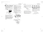
Attaching the air intake panel
• Loosen the screw of the air intake grille fixing plate
on the centre of the panel. Slide the plate to the
direction of “OPEN“ arrow shows.
• Push the “PUSH” indicating parts (3 positions) of the
air intake grille to open while holding the air intake
grille with hands.
▼
Fig. 6 Opening / Closing of air intake grille
and louver
• Pass the louver motor wire connectors (White) from
the ceiling panel and the electrical control box
through the wiring hole of the ceiling panel to
connect.
• Check that wires are not pinched between the ceiling
panel and the indoor unit, and between the ceiling
panel and the ceiling surface, and then mount the
ceiling panel fixing screw in the procedure below.
(Tightening order of ceiling panel fixing screws)
(Tighten screws in order of numbers shown in
Figure.)
1
Temporal fixing at center of the ceiling
panel. ((1))
2
Check and adjust the installation position.
3
Temporal fixing at left side of the ceiling
panel. ((2) to (3))
4
Temporal fixing at right side of the ceiling
panel. ((4) to (5))
5
Check installation position and wires.
6
Secure tightening of (1), (2), (3), (4), (5).
• After tightening the ceiling panel fixing screws,
mount the caps at two positions of air discharge side.
((6) to (7) in Figure)
▼
Fig. 7 Mounting procedure of ceiling panel
fixing screws
• Store louver motor wires in the wiring hole.
▼
Fig. 8 Processing of louver motor wire
(Details of A part)
PUSH
PUSH
PUSH
Air intake grille
Louver
OPEN
Å
LOCK
Æ
(2)
(6)
(3)
(1)
(7)
(4)
(5)
Louver
motor wire
Attached
cap
Ceiling panel
fixing screw
Louver motor wire
Wiring hole
• Hang strings (To prevent falling) of the air intake
grille to the hanging hole at the center of air intake of
the indoor unit.
▼
Fig. 9 Mounting of string of air intake grille
(B view)
• Check that the air filter is surely installed.
• Close air intake grille. Slide air intake fixing plate to
the direction of “LOCK“ arrow shows and fix it with a
screw.
• Push the “PUSH” indicating parts to close the air
intake grille so that strings are not pinched between
the air intake grille and the ceiling panel.
5
Other Information
Confirmation after installation
• Confirm that there are no gaps between the
indoor unit and the ceiling panel, or between the
ceiling panel and the ceiling.
Gaps may allow water leakage or condensation to
occur.
• Confirm that all wires are connected properly.
Improper connection will result in malfunction of the
louvers.
• Confirm the air filter installed.
Hanging hole
String
Ceiling
Ceiling panel
There should be no clearance.
Indoor unit
5-EN
6-EN
+00EH99518201.book Page 3 Monday, April 25, 2011 10:45 AM


