– 13 –
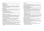
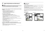
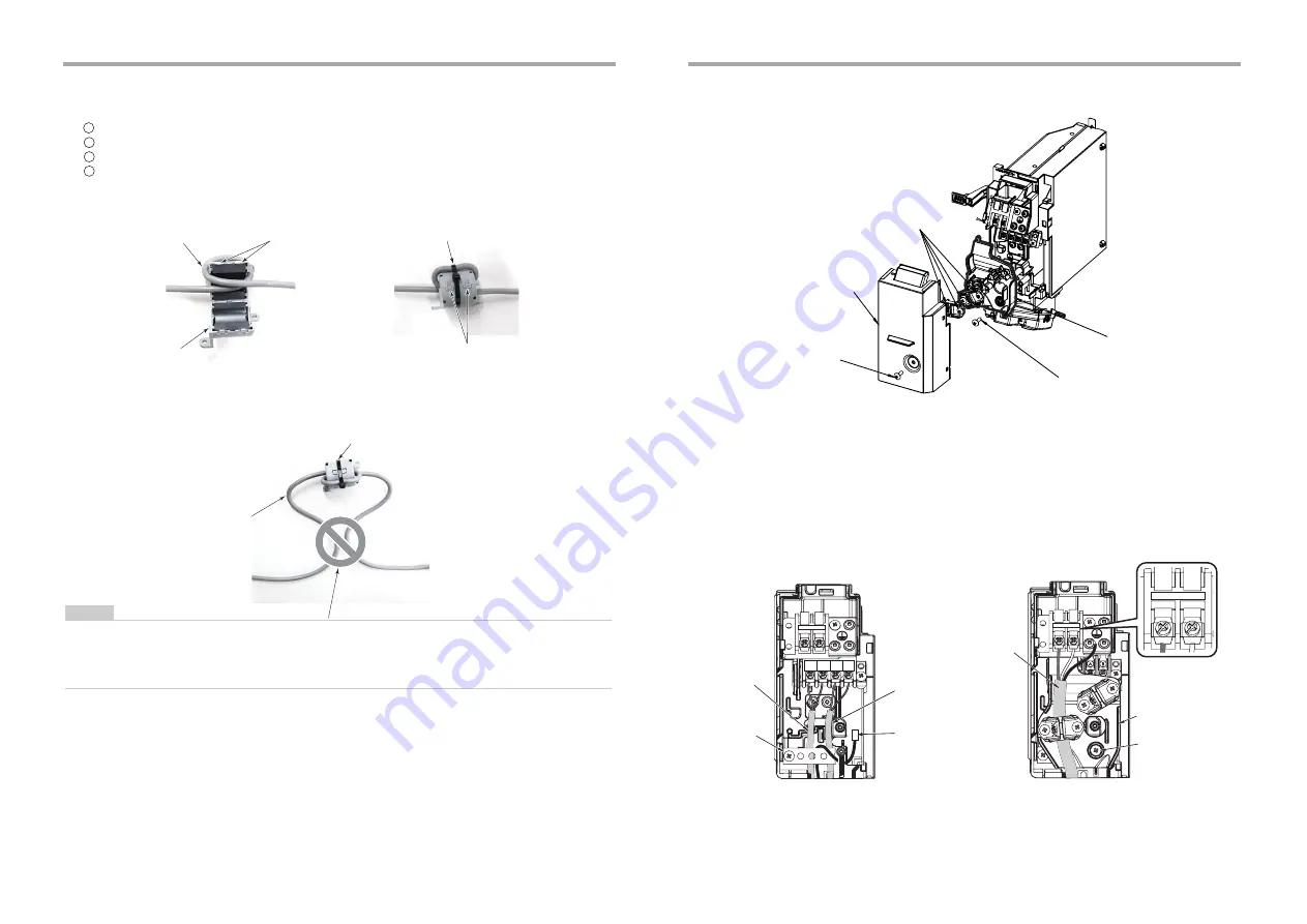
3) Be sure to install a clamp filter (accessory) on the PMV Kit side and another clamp filter (accessory) on the
indoor unit side.
Take off claws of the clamp filter at 2 positions.
Pass the connection cable 2 times from the PMV Kit main body around the inner part of the clamp filter.
Tighten claws of the clamp filter securely and then lock it.
Use the attached binding band to bundle the clamp filter together with connection cable.
1
2
3
4
NOTE
• Route the cable in such a way that its portions before and after the clamp filter do not come into contact with
each other.
• When an air-conditioner is operated, with a clamp filter (accessories) not attached, it may become the
malfunction of an electronic device and the cause of failure in the circumference.
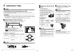
Claws
2 passes (1 turn)
Pass the lead wire through the clamp filter
as shown in the picture below.
Clamp filter (Accessory)
(Model name: E04SR401938)
Binding band M
Lock securely with claws
Incorrect wiring pattern
Clamp filter (Accessory)
Connection cable to PMV Kit
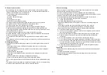
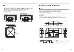
4) After turning off the power supply, remove the terminal cover and the clamp base.
5) Replace the PMV connector built in the indoor unit with the connection cable of PMV Kit.
The lock mechanism is provided at side of PMV connector. Remove the connector by releasing the lock
mechanism.
6) The connector of PMV Kit connecting cable is inserted in an indoor unit connector (CN82).
7) Fix the connection cable of PMV Kit with cord clamp for Indoor / Outdoor control wiring and remote controller
wiring.
8) Mount the terminal cover and then the work completes.
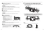
Screw
<Removing the terminal cover and the clamp base>
Screw
Terminal cover
Screw
Clamp base
A
Uv(U
1
)
B
Uv(U
2
)
R
(L)
S
(N)
R
(L)
S
(N)
R
(L)
S
(N)
Indoor / Outdoor
control wiring
<Connecting connection cable of PMV Kit.>
Cord clamp
Installation place
for PMV connector
(blue, CN82)
Power wiring
Clamp base
Clamp base
fixing screw
Remote
controller wiring
25-EN
26-EN

