– 15 –
<Compact 4-way Cassette type>
9) Using an attached binding band S, put together the removed PMV lead wires and then store them in the
electrical parts box.
10) Mount the electrical parts box cover so as not to pinch wiring, and the work completes.
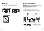
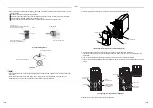
P.C. board
Installation place for PMV connector
(Blue, CN82)
Cord clamp
* Fixed the connection cable
of PMV Kit
Wire clamp
* Pass the connection
cable of PMV Kit
<Connecting connection cable of PMV Kit.>
Connection cable of PMV Kit
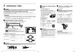
Power wiring
Clamp filter (Accessory)
Indoor / Outdoor
control wiring
Remote controller wiring
• Work procedure 3
Applicable model: All the indoor units except work procedure 1
and 2
<PMV Kit connection wiring method>
• To comply with the EMC (Electromagnetic Compatibility) standards, be sure to use the clamp filters that are
supplied accessories.
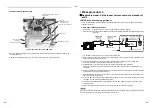
Clamp filter installation positions
• PMV Kit side:
A position 500 mm or less away from the shell of the PMV Kit body.
• Indoor unit side: A position between the PMV Kit body and the existing clamp filter and adjacent to the existing
clamp filter.
1) ~2) Perform the same process as 1) and 2) of Work procedure 1.
3) Be sure to install a clamp filter (accessory) on the PMV Kit side. The operation in this step is the same as the
operation in step 3) of Work procedure 1.
4) Open the electrical parts box cover of the indoor unit after power-off and then process wiring work.
For details, refer to the Installation Manual attached to the indoor unit.
5) Replace the PMV connector built in the indoor unit with the connection cable of PMV Kit.
The lock mechanism is provided at side of PMV connector. Remove the connector by releasing the lock
mechanism.
6) Be sure to install another clamp filter (accessory) on the indoor unit side. The operation in this step is the same
as the operation in step 3) of Work procedure 1.
7) Route the PMV Kit connection cable in such a way that its portions before and after the clamp filter do not
come into contact with each other.
8) Secure the PMV Kit connection cable together with the Indoor / Outdoor control wiring by using the existing
cord clamp or a commercially available binding band.
9) Using an attached binding band S, put together the removed PMV lead wires and then store them in the
electrical parts box.
10) Mount the electrical parts box cover so as not to pinch wiring, and the work completes.
NOTE
When an air-conditioner is operated, with a clamp filter (accessories) not attached, it may become the malfunction
of an electronic device and the cause of failure in the circumference.
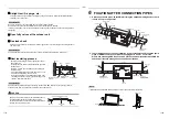
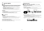
Connection cable
Indoor unit
Clamp filter
(Accessory)
Clamp filter
(Already
installed)
PMV Kit side
Indoor unit side
Clamp filter
(Accessory)
Pulse motor valve (PMV)
CN82
connector
PMV lead wires
Indoor control P.C. board
PMV
PMV Kit
500 mm or less
500 mm or less
29-EN
30-EN


