– 10 –
5
REFRIGERANT PIPING
WARNING
If refrigerant gas has leaked during the installation work, ventilate the room immediately.
If the leaked refrigerant gas comes in contact with fire, noxious gas may be generated.
After the installation work, confirm that refrigerant gas does not leak.
If refrigerant gas leaks into the room and flows near a fire source, such as a fan heater, cooking stove or
heating unit, noxious gas may be generated.
REQUIREMENT
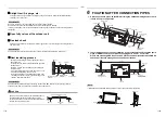
• In case of a long pipe, provide support brackets with interval of 1.5 - 2 m in order to prevent noise from the pipe.
• When installing the PMV Kit, provide support brackets on the pipe at the both side of the PMV Kit to fix it regardless
of the pipe length.
*For the details, refer to the
6 FIXATION AFTER CONNECTION PIPES (page 11)
in this manual.
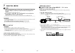
Allowable length of refrigerant piping
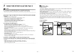
The straight pipe section should be at least 0.2 m as shown in the figure below.
* Short length of the straight pipe section may cause abnormal sounds.
Piping material and dimensions
CAUTION
CAUTION
When connecting Dia.9.5 refrigerant pipes, be sure to insert a seal pipe between PMV main unit and the joint.
If the seal pipe is not inserted, refrigerant leakage is caused.
Model name
Indoor unit capacity type Diameter of refrigerant pipe
Notes
RBM-PMV0361U-E
003, 005, 007,
009, 012 type
6.4
RBM-PMV0901U-E
014, 015, 018 type
6.4
020, 024, 027,
030, 034 type
9.5
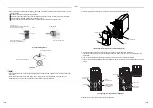
0.2 m or more
2 m to 10 m
(5 m or longer is more effective.)
PMV Kit
Refrigerant pipe
Indoor unit
Label
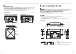
• Connecting direction of refrigerant pipe
When connecting pipes, be careful of direction of the main unit.
Be sure to install the main unit so that
[
] mark on the label directs upward.
For connection of the refrigerant pipes, follow the arrow mark on the label
and connect pipes after confirming directions of the indoor unit and the
outdoor unit.
Attached joint
Attached joint
Attached joint
Liquid pipe
Attached joint
Seal pipe
PMV Kit
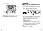
Pipe forming / End positioning
Flaring
1.
Cut the pipe with a pipe cutter.
Remove burrs completely.
Remaining burrs may cause gas leakage.
2.
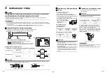
Insert a flare nut into the pipe, and flare the pipe.
As the flaring sizes of R32 or R410A differ from those
of refrigerant R22, the flare tools newly
manufactured for R32 or R410A are recommended.
However, the conventional
tools can be used by adjusting
projection margin of the
copper pipe.
▼
Projection margin in
flaring: B (Unit: mm)
Rigid (Clutch type)
▼
Flaring diameter size: A (Unit: mm)
CAUTION
CAUTION
• Do not scratch the inner surface of the flared part
when removing burrs.
• Flare processing under the condition of scratches on
the inner surface of flare processing part will cause
refrigerant gas leak.
• Check that the flared part is not scratched, deformed,
stepped, or flattened, and that there are no chips
adhered or other problems, after flare processing.
• Do not apply refrigerating machine oil to the flare
surface.
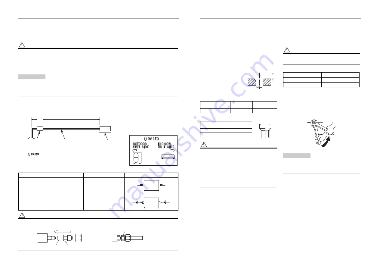
Connection of refrigerant pipe
Connect all the refrigerant pipes with flare
connecting work.
CAUTION
CAUTION
Do not apply excessive torque. Otherwise, the nut may
crack depending on the conditions.
▼
Tightening torque of flare pipe connections
Incorrect connections may cause not only a gas leak,
but also a trouble of the refrigeration cycle.
Align the centers of the connecting pipes and tighten
the flare nut as far as possible with your fingers. Then
tighten the nut with wrenches and torque wrench as
shown in the figure.
REQUIREMENT
Tightening with an excessive torque may crack the nut
depending on installation conditions.
Tighten the nut within the specified tightening torque.
Outside diameter
size
R32 or R410A
tool used
Conventional
tool used
6.4, 9.5
0 - 0.5
1.0 - 1.5
Outside diameter
size
A
+0
–0.4
6.4
9.1
9.5
13.2
B
A
Unit: N•m
Outside diameter size
Tightening torque
6.4 mm
14 - 18
9.5 mm
34 - 42
Work using two wrenches
19-EN
20-EN

