background image


184 

RemotEye 4 User Manual – 90988-007 

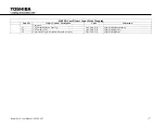
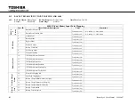
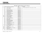
4400 BACnet Binary Input Point Mapping


Inst. ID 

Object Name & Description 

Units 

Comments 

47 

Inverter Voltage Abnormal 

True/False (1/0) 


48 

Output Voltage Abnormal 

True/False (1/0) 


49 

Current Abnormal 

True/False (1/0) 


50 

Inverter Output Voltage Abnormal 

True/False (1/0) 


51 

Gate Voltage Lost 

True/False (1/0) 


52 

Inverter Current Error 

True/False (1/0) 


53 

Inverter Bypass Voltage Mismatch 

True/False (1/0) 


54 

No Control Connection 

True/False (1/0) 


Warnin

gs


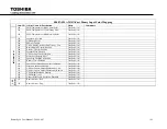
55 

Input Voltage Error 

True/False (1/0) 


56 

Input Frequency Error Warning 

True/False (1/0) 


57 

On Bypass 

True/False (1/0) 


58 

Bypass is Enabled 

True/False (1/0) 


59 

Bypass Input Frequency Error Warning 

True/False (1/0) 


60 

Bypass Error 

True/False (1/0) 


61 

Output Load Exceeded 

True/False (1/0) 


62 

Inverter Overload Warning 

True/False (1/0) 


63 

Inverter Output Voltage Out of Spec 

True/False (1/0) 


64 

Output Overload Warning 

True/False (1/0) 


65 

Ouput Overload Exceeded 110% 

True/False (1/0) 


66 

User Defined Overload Warning 

True/False (1/0) 


67 

Output Frequency is set at 50Hz 

True/False (1/0) 


68 

Current Limit Warning 

True/False (1/0) 


69 

Output Current Exceeded 

True/False (1/0) 


70 

Battery Test In Progress 

True/False (1/0) 


71 

Battery Test Failed Warning 

True/False (1/0) 


Summary of Contents for RemotEye 4

Page 1: ...RemotEye 4 User Manual Document Number 90988 007 September 2018 ...

Page 2: ...g operating or performing maintenance on this equipment The information in this manual is subject to change without notice The Toshiba International Corporation shall not be liable for direct indirect special or consequential damages resulting from the use of the information contained within this manual This manual is copyrighted No part of this manual may be photocopied or reproduced in any form ...

Page 3: ...eate new warranties or modify the existing warranty Any electrical or mechanical modifications to this equipment without prior written consent of the TOSHIBA International Corporation will void all warranties and may void the UL CUL listing or other safety certifications Unauthorized modifications may also result in equipment damage or personal injury When used on UPS supporting safety critical eq...

Page 4: ...4 RemotEye 4 User Manual 90988 007 This Page Intentionally Left Blank ...

Page 5: ...eset Button 18 FEATURES 20 2 6 1 HTTP Web Access 20 2 6 2 SNMP Access 20 2 6 3 BACnet and Modbus Access 21 2 6 4 Additional Features 21 2 6 5 RemotEye 4 Support Software Programs 22 2 6 6 Optional Environmental Monitoring Device EMD 22 2 6 7 Optional RemotEye Sensor Pack for EMD 23 2 6 8 Optional RemotRadar Software 23 3 SETUP 24 CHECKLIST 24 INSTALL REMOTEYE 4 IN UPS 25 4 REMOTEYE 4 NETWORK CONNE...

Page 6: ...NMENTAL MONITORING DEVICE 58 7 6 1 EMD Installation 59 7 6 2 EMD Parameters 59 7 6 3 EMD Configuration 60 8 MOBILE FRIENDLY WEB INTERFACE 61 DISPLAY AND NAVIGATION 61 ALERT CENTER 62 PROTECTED CLIENTS 62 9 REMOTEYE 4 CONSOLE MENU NAVIGATION 63 MAIN MENU DESCRIPTION 66 REMOTEYE 4 CARD SETTINGS 67 9 2 1 IP Time and System Group 68 9 2 2 Network Control Group 70 9 2 3 Account Control Group 73 9 2 4 E...

Page 7: ...00 AND 5000 SERIES UPS MONITORING 121 A 3 MODBUS 3X INPUT REGISTERS FOR SINGLE PHASE UPS MONITORING 131 A 4 MODBUS 1X INPUT REGISTERS FOR THREE PHASE UPS ALARMS AND STATUS 143 A 5 MODBUS 1X INPUT REGISTERS FOR SINGLE PHASE UPS ALARMS AND STATUS 152 APPENDIX B BACNET POINT MAPPING FOR 1600XP XPI 163 B 1 BACNET ANALOG INPUT POINT MAPPING FOR 1600XP XPI 163 B 2 BACNET BINARY INPUT POINT MAPPING FOR 1...

Page 8: ... FOR G9000 G2020 V2 216 J 1 BACNET ANALOG INPUT POINT MAPPING FOR G9000 G2020 V2 216 I 2 BACNET BINARY INPUT POINT MAPPING FOR G9000 G2020 V2 219 APPENDIX K SNMP MIB OID S FOR 1600XP XPI 222 APPENDIX L SNMP MIB OID S FOR 4300 228 APPENDIX M SNMP MIB OID S FOR 4400 233 APPENDIX N SNMP MIB OID S FOR G9000 G2020 238 APPENDIX O SNMP MIB OID S FOR 5000 NEMA 3R 241 APPENDIX P SNMP MIB OID S FOR T1000 24...

Page 9: ...ams RVFD 41 Figure 5 8 Dynamic Comprehensive Block by Series 41 Figure 5 9 History Trend Blocks 42 Figure 5 10 Login to Edit Dashboard 42 Figure 5 11 Edit Dashboard Button 42 Figure 5 12 Edit Dashboard Mode 43 Figure 5 13 Edit Dashboard Mode Drop down Menu 44 Figure 5 14 Drop Down Menus 45 Figure 5 15 SETTINGS Web Page 45 Figure 6 1 SNMP Settings Panel 47 Figure 6 2 Modbus TCP IP and BACnet IP Con...

Page 10: ... 11 1 Network with RemotEye and ESXi Servers 91 Figure 11 2 Text turns RED in Super User Mode 92 Figure 11 3 Add Server to vMA 92 Figure 11 4 ESXi Added to VMA 92 Figure 11 5 WinSCP Login Screen 93 Figure 11 6 WinSCP vi admin Screen 94 Figure 11 7 Install Screen Shot 95 Figure 11 8 Protected Client Table in RemotEye 95 Figure 11 9 vSphere Management Asistant Screen Shot 96 Figure 11 10 VM Remote S...

Page 11: ...rs 59 Table 9 1 Console Menu Tree 63 Table 10 1 History Log Availability 81 Table 10 2 UPS History Summary Page Availability 81 Table 10 4 RemotEye 4 UPS Warning Codes 89 Table 11 1 Tupgrade Toolbar Functions 105 Table 12 1 RemotEye 4 System Specifications 106 Table 12 2 RemotEye 4 LED Indications 107 Table 12 3 Firmware Specifications 108 Table 12 4 Pin outs for Network RJ 45 108 Table 12 5 Pin o...

Page 12: ...12 RemotEye 4 User Manual 90988 007 This Page Intentionally Left Blank ...

Page 13: ...o personnel The word WARNING in capital letters preceded by the safety alert symbol indicates that a potentially hazardous situation exists that if not avoided could result in death or serious injury to personnel The word CAUTION or ATTENTION in capital letters preceded by the safety alert symbol indicates that a potentially hazardous situation exists which if not avoided may result in minor or mo...

Page 14: ...ge or death if the instructions are not followed Misuse of this equipment could result in injury and equipment damage In no event will Toshiba Corporation be responsible or liable for either indirect or consequential damage or injury that may result from the misuse of this equipment INSTALLATION PRECAUTIONS Install the unit in a stable level and upright position that is free of excessive vibration...

Page 15: ...work 2 Manually configure the RemotEye 4 circuit card using either default settings or manually selected settings a The default network values are used and the network is changed to accommodate these values b The RemotEye 4 IP address values are to be manually input to accommodate the existing network configuration APPLICABLE SPECIFICATIONS Electronic Emission Notice Federal Communications Commiss...

Page 16: ...kVA Three Phase to Single Phase UPS Family G9000 G2020 80 1000kVA Three Phase UPS Family PACKAGE CONTENTS Listed below are the items included in the RemotEye 4 package 1 The RemotEye 4 printed circuit board 2 USB cable USB A to USB Mini B 3 A CD ROM containing the following a The RemotEye 4 Quick Installation Guide b RemotEye 4 User Manual c T1000 MIB File d T1000 1 3kVA MIB File e 1600XP XPi MIB ...

Page 17: ...arts RemotEye 4 display only Does not restart the UPS The Restart button is behind faceplate under the network port It can be accessed with a thin probe inserted through the Restart port Press 1 second Restart RemotEye 4 This does not affect the operation of UPS 7 Hard Reset button Behind faceplate The Hard Reset button is located behind the RemotEye 4 faceplate beneath the USB port Remove the fac...

Page 18: ...PCB card may be safely removed and re inserted into the UPS PCB mounting box while the UPS is energized 1 Remove the RemotEye 4 PCB from the UPS PCB mounting box while the UPS is energized 2 Remove the PCB faceplate Use a Philips screwdriver to unscrew the Philips head screw Figure 2 2 B from the press nut in the Faceplate Bracket Figure 2 2 A 3 Insert the PCB without the faceplate into the PCB mo...

Page 19: ...ffic 2 OFF Flashing 1sec Ethernet 10 Traffic 3 ON ON 100 Base TX Ready 4 OFF ON 10 Base T Ready 5 OFF OFF Ethernet Disconnection 6 Status EMD ON OFF Power On Normal Status 7 ON Flashing 1 3sec RS232 Port Activity UPS site 8 Two LED cross Flashing Two LED cross Flashing Auto Diagnostic Mode 9 ON ON Auto Diagnostic Failed 10 OFF OFF Hardware Error Green LED Yellow LED Green LED Yellow LED ...

Page 20: ...y of various parameter groups in an array of replaceable rearrangeable information blocks or widgets Figure 2 4 HTTP Web Access Dashboard Example 2 6 2 SNMP Access RemotEye 4 provides enhanced SNMP security with option of SNMPv3 RemotEye 4 also supports SNMPv1 and SNMPv2c It is compatible with the United States Standard UPS MIB RFC1628 and Toshiba customized MIB files See SNMP example using iReaso...

Page 21: ...e one config file and configure all RemotEye 4 s at once It also allows troubleshooting to be expedited UPS Home Group RemotEye 4 can see other RemotEye 4s that are in the same network as well as view the UPS mode on line Bypass or Backup of the corresponding attached UPS A super user or Administrator can reset the password of users The web page automatically logs out user after 15 minutes of inac...

Page 22: ... shutdown of ESXi servers can be accomplished by installing the separate program RemotEye ESXi Client Shutdown Daemon The program is software that is installed onto the ESXi server This allows the RemotEye 4 to communicate with the Client Software to broadcast system failure messages via an IP Internet Protocol packet and to perform unattended graceful shutdown of up to 250 clients See Section 11 ...

Page 23: ...tion Part Number RMTI EMD SENSORS Figure 2 7 EMD Sensor Pack 2 6 8 Optional RemotRadar Software RemotRadar Global Monitoring Software Sold Separately is a real time monitoring solution software application that allows monitoring up to 5 000 RemotEye II III 4s all at once See Figure 2 8 RemotRadar Version 2 0 Example It also has the ability to send SMS and Email notifications when an event occurs t...

Page 24: ...en installing the RemotEye 4 in a 1600XP XPi you will also need the ADMIN password Record the relevant information in the Set up Checklist Table 3 1 to facilitate installation and subsequent troubleshooting Table 3 1 Set up Checklist Example values shown are factory provided default values Item Setting Recorded Setting 1 RemotEye 4 MAC Address see Figure 3 1 Default 00E0D8LLMMNN 2 IP Address Defau...

Page 25: ...otEye 4 is produced by the same manufacturer these 3 hexadecimal bytes remain constant The LL MM NN characters identify the serial number of the device in hexadecimal form The serial number is unique for each RemotEye 4 device Figure 3 1 RemotEye 4 MAC Address Location 2 Ensure the UPS is turned off using the proper shutdown procedure as explained in the UPS manual 3 Slide the RemotEye 4 card asse...

Page 26: ...otEye 4 User Manual 90988 007 Figure 3 3 RemotEye 4 in 4300 and 4400 UPS Figure 3 4 RemotEye 4 in G9000 G2020 UPS NOTE RemotEye 4 located on back side of the Control Section door of for all 100 750kVA models ...

Page 27: ...RemotEye 4 User Manual 90988 007 27 Figure 3 5 RemotEye 4 in G9000 1000 2000kVA Open Control Section Door to access RemotEye 4 ...

Page 28: ...28 RemotEye 4 User Manual 90988 007 Figure 3 6 RemotEye 4 in 5000 Series 30kVA ...

Page 29: ...RemotEye 4 User Manual 90988 007 29 Figure 3 7 RemotEye 4 in T1000 1 3kVA Series Rackmounts Figure 3 8 RemotEye 4 in T1000 1 3kVA Series Towers ...

Page 30: ...30 RemotEye 4 User Manual 90988 007 Figure 3 9 RemotEye 4 in 5000 3P1 Inside of Power Electronics Cabinet in top right corner ...

Page 31: ...5 RS 232 or Serial Terminal Block RS 485 Terminal Emulation Software Using the web interface is the preferred method of setting up and working with the RemotEye 4 Alternatives are briefly discussed at the end of this section IP ADDRESS SETUP WITH DHCP The only data required for the network is the RemotEye 4 MAC address See Table 3 1 Set up Checklist Each Ethernet network is different Use the follo...

Page 32: ... 4 2 1 Install USB Driver Windows 8 1 1 Connect the USB Cable between PC and RemotEye 4 Setup port 2 Insert the factory provided CD in the PC CD Drive 3 Go to the PC Settings Tab and click the Change PC Settings button 4 Click the Update and Recovery Option and select the following Recovery Option Click the Restart now button under Advanced Startup 5 Wait for computer to restart Choose the Trouble...

Page 33: ... port will appear under a different name in some systems If SPEAr doesn t appear when performing the following steps check to ensure that it isn t appearing under a different name in the Ports section of the Device Manager Figure 4 2 PC to RemotEye 4 USB mini USB Cable Adapter 4 2 3 Establishing Comminication Terminal Emulation Software The PC must be running Terminal Emulation Software TES such a...

Page 34: ... network See Section 4 2 3 Set the IP Address 4 2 4 Set the IP Address 1 Install the Driver 2 Connect the USB to mini USB adapter cable provided in the RemotEye 4 package 3 Load and start a hyperterminal Tera Term 4 Look for the SPEAr COM Port number 5 Click OK 6 Set the COM port for SPEAr to the following settings Baud 9600 baud Data 8 bit Parity None Stop bit 1 bit Flow Control None 7 Login The ...

Page 35: ...m Group 1 IPv4 Group 10 2 Enter the IP Network Mask etc 11 Exit Console 0 Return to previous menu 0 Return to previous menu p 0 Return to previous menu 0 Back to Main Menu 0 Exit 12 Log off 13 Connect RemotEye 4 to the network switch router hub with Cat 5 cable 14 Open web browser 15 Type in IP address assigned in Step 10 2 16 On log in page click on First Time Setup Default User is TOSHIBA the de...

Page 36: ...for 60 seconds RemotEye 4 will terminate the connection The first time setup replaces the default Username TOSHIBA and Password ADMIN with the users selected administrative level account name and password Open up web browser and enter the assigned RemotEye 4 IP address into the URL text Thereafter the choices to login will be either in The user will be greeted with a welcoming web page when opened...

Page 37: ...HIBA System Contact Enter System Contact Default Technical Support Team System Location Enter system location Default IP Address Enter IPv4 Address Display default IP or the assigned IP address from BOOTP DHCP server or from the console settings setup Default 192 168 1 168 Gateway Address Enter Gateway Address Display default gateway IP or the assigned Gateway IP address from BOOTP DHCP server or ...

Page 38: ...efault 64 BootP DHCP Control Select to Disable Enable BootP DHCP Control protocol o Default Disabled if no BOOTP DHCP server was found in the network If BOOTP DHCP server is found in network show enabled Telnet Control Select to Disable Enable Telnet Control protocol Default Disabled SSHv2 Control Select to Disable Enable SSHv2 Control protocol Default Enabled Press Finish Figure 5 4 First Time Se...

Page 39: ...and five are interchangeable from a selection of over a dozen parameter groupings The five reserved blocks are Default Picture Custom Photo This block will automatically display the default picture of the UPS the RemotEye 4 is attached to The user may replace the default picture by uploading their own picture one JPG picture only 100kb max by pressing the Picture icon button History Graph Widget D...

Page 40: ...020 5000 3P1 Rackmount Tower Figure 5 6 Default UPS Pictures Remote View Flow Diagram RVFD This widget displays a graphical diagram of the current UPS mode Startup Online CVC Bypass Backup Battery Test Pre Charge Gate Check or Shutdown mode Startup Mode Online Mode CVC Mode Bypass Mode Backup Mode Battery Test Mode ...

Page 41: ...rer UPS Typeform Specific model number UPS Serial Number and UPS System Name assigned by the user This information is constant This widget cannot be replaced History Trend Block This block can only be set to display either the History Graph or Trend Graph This block cannot be replaced History Block Default The time can be controlled by the user by entering the Start Date and End Date The graph wil...

Page 42: ... log in as an administrator either through the log in web page or the log in button if signed in as guest see Figure 5 10 Login to Edit Dashboard User Login Guest Login Figure 5 10 Login to Edit Dashboard 2 Login then press the Edit Dashboard button Figure 5 11 Figure 5 11 Edit Dashboard Button The dashboard will place a white X in the upper right corner of all widgets that can be edited See Figur...

Page 43: ...RemotEye 4 User Manual 90988 007 43 Figure 5 12 Edit Dashboard Mode White X Selectable Reserved Reserved Reserved Reserved Selectable Selectable Selectable Selectable Selectable ...

Page 44: ...no drop down menu Clicking this reloads the dashboard UPS MONITORING Drop down menu allows monitoring of specific categories of UPS Parameters UPS MANAGEMENT Drop down menu allows user management of UPS functions The menu only shows when a UPS is connected to the RemotEye 4 SETTINGS Drop down menu allows setting the protocols parameters network addresses for the RemotEye 4 EMD Drop down menu allow...

Page 45: ...e of the display Figure 5 15 SETTINGS Web Page 5 3 1 UPS MONITORING Drop down Menu Ref Figure 5 14 Drop Down Menus This is a comprehensive of all drop down menus Note Not all options apply to all models of UPS s UPS Data General UPS hardware and software version information UPS Data Display UPS Display firmware version information UPS Data Other Internal communications and port status Input Parame...

Page 46: ...Events Shutdown Action Shutdown Delay Non Recurring On Off UPS Shutdown Scheduler 5 3 3 SETTTINGS Drop down Menu These settings can be accessed from the SETTINGS menu Ref Figure 5 14 Drop Down Menus This is a comprehensive of all SETTINGS options Note Not all options apply to all models of UPS s SNMP Settings Configure RemotEye 4 to work with SNMP Modbus Settings Configure RemotEye 4 to work with ...

Page 47: ...s in the SNMP Settings panel For SNMP Traps select the appropriate settings under SNMP TRAP Receivers by entering the IP address etc and selecting from the corresponding drop down menus for Trap Severity Level and Version 3 Click the Set button Figure 6 1 SNMP Settings Panel The RemotEye 4 supports SNMP ver 1 ver 2c and ver 3 Any workstation with compat1ble SNMP management software can manage moni...

Page 48: ...ctory supplied CD ROM These files describe the information that is attainable from each Toshiba UPS The Toshiba MIB files must be manually entered imported or compiled into the Manger database For instruction on incorporating private MIB files into the Manager consult the Manager Software documentation 6 1 2 2 MIB Import Example This example shows how to incorporate the Toshiba MIB into the Manage...

Page 49: ...6 2 Modbus TCP IP and BACnet IP Configuration Panels 1 On the home page dashboard click on the SETTINGS menu at the top of the page This will bring up the SETTINGS drop down menu See Figure 5 14 Figure 6 2 2 In the SETTINGS drop down menu click on BACnet Settings the selected entry text will turn RED 3 Look In the Protocol Settings Panel titled BACnet Settings Under BACnet IP Settings set BACnet I...

Page 50: ...f the page This will bring up the SETTINGS drop down menu See Figure 6 4 3 In the SETTINGS drop down menu click on Interface Settings the selected entry text will turn RED 3 1 If using RS 485 3 1 1 Under RS 485 Interface Settings set RS 485 Interface Enable Disable to Enabled and set Define RS 485 Interface Protocol to Modbus 3 1 2 Under RS 232 Interface Settings set RS 232 Interface Enable Disabl...

Page 51: ...nit address Default 1 6 Under Modbus TCP IP Settings set Modbus TCP IP to Disabled 7 Click the Set button Figure 6 5 Modbus Settings for Modbus RTU 8 Configure the Connection Setup with master as follows 8 1 Connection Serial Port 8 2 Port Settings Port 1 9600 Baud 8Data bits Non Parity 1 Stop bit 8 3 Mode RTU 8 4 Slave ID 1 There can be from 1 247 Slave units each with a unique ID connected to ea...

Page 52: ...or BACnet MS TP Serial communication protocols require additional configuration with the INTERFACE configuration panel Ref Table 12 6 Pin outs for RS 485 Phoenix Connector HARDWARE CONNECTIONS 1 Wire the RemotEye 4 Phoenix connector for the RS 485 Serial port to the serial input cables as follows ...

Page 53: ...Disabled and set Define RS 232 Interface Protocol to Disabled 3 2 If using RS 232 3 2 1 Under RS 232Interface Settings set RS 232 Interface Enable Disable to Enabled and set Define RS 232 Interface Protocol to BACnet 3 2 2 Under RS 485Interface Settings set RS 485 Interface Enable Disable to Disabled and set Define RS 485 Interface Protocol to Disabled Figure 6 9 Interface Settings for BACnet MS T...

Page 54: ...itional RS 485 Connection Information reference Appendix P 6 3 3 Suggested Communication Settings All Protocols Modbus TCP Modbus RTU BACnet MS TP BACnet IP Reply Timeout 500ms Delay Time 1 second Min Delay between polls If you set this value lower than 1 second the time gap between response and a new request cannot be guaranteed This is because the scheduler switch tasks every 10 20ms ...

Page 55: ...imes EMAIL NOTIFICATION This page allows the administrator to set the RemotEye 4 email notification configuration parameters Click on Settings at the top of the webpage and on the dropdown menu select Email Settings SMTP Server This field allows the administrator to set the IP Address or Hostname of a Simple Mail Transfer Protocol SMTP mail server that will be used to send email messages from Remo...

Page 56: ...res attention This is based on which Warning alarms are selected in the UPS Configuration General page Will also receive fault alarms o Fault UPS has encountered a critical abnormal condition and requires attention This is based on which Fault alarms are selected in the UPS Configuration General page Refer to the manual for possible causes and solutions Will only receive fault alarms Description A...

Page 57: ...wireless adapter Edimax EW 7811Un is necessary for wireless functionality Edimax is a trademark of Edimax Technology Co Ltd REMOTEYE 4 SYSTEM SETTINGS The editable system settings for RemotEye 4 are listed below 1 Date Time Settings 2 System Network Settings 2 1 RemotEye 4 information 2 2 RemotEye 4 IPv4 Setting 2 3 RemotEye 4 IPv6 Settings 2 4 Protocols Settings 2 4 1 DHCP Control 2 4 2 Telnet 2 ...

Page 58: ...e monitoring of environment temperature environment humidity and other environmental conditions via a web browser and SNMP The EMD also provides two user defined dry contacts for additional environmental monitoring These dry contacts can be used with devices that provide normally open or normally closed results such as door sensors smoke detectors motion detectors and liquid detectors The EMD is c...

Page 59: ... status based on the administrator configurable threshold The list below indicates the parameter status Table 7 2 EMD Layout and Indicators EMD Comprehensive View Parameter Value EMD Name Assigned ID Displays the EMD Name when the EMD is connected and working correctly Disable When the EMD is connected but the Device Status is Disabled in the EMD configuration settings Unknown When the EMD is not ...

Page 60: ...2 the hysteresis can be used to adjust the sensitivity of an alarm The alarm will be active or inactive only after the alarm stays in the same state for the duration of the hysteresis value in seconds For example if the hysteresis is 5 for an alarm the alarm will NOT activate until the same state has persisted for 5 seconds This ruling also applies in reverse so that the alarm has to stay in an in...

Page 61: ... display for the mobile app is shown in Figure 8 1 Tap on the drop down menu icon three horizontal parallel lines at the top left side of the display to open the drop down menu H3BG2L060C61T 1600XPi 6KVA Typeform T1S0A1000AXA UPS Model T1000 1kVA UPS Name Computer Room Input Power Config 120V 60Hz Input of Lines 1 Input V 114 95 Input Current Amps 3 8 51 Input Hz 59 0 Input Apparent VA 458 Output ...

Page 62: ...1600XP XPi 4300 4400 G9000 T1000 Figure 8 2 Input Parameters Mobile Webpage Examples ALERT CENTER The alarm symbol will pop up in the UPS Identification window header whenever there is an alert generated by the UPS Click on the drop down menu and select Alert Center More detailed information on the alert will be displayed See Figure 8 3 Figure 8 3 Example of Alert Center and Protected Clients PROT...

Page 63: ... 3 Network Subnet Default 255 255 255 0 0 Return to previous menu 2 IPv6 Group 1 IP v6 Link Local Address Default FE80 2E0 D8FF FEFF AFE2 2 IPv6 Global Address Default 2001 B182 2E0 D8FF FEFF A 3 IPv6 Prefix Length Default 64 4 IPv6 Router Address Default FE80 218 E7EE FEF4 BD26 0 Return to previous menu 3 Date and Time Group 1 System Date mm dd yyyy 02 12 2014 2 System Time hh mm ss 21 56 43 3 NT...

Page 64: ...Return to previous menu 3 Account Control Group 1 RADIUS Group 1 RADIUS Port 2 RADIUS Server Settings 3 Packet Timeout 1 4 Packet Retry 3 0 Return to previous menu 2 Access Control Table User Name User Level 1 Disabled 2 to 8 Command 1 Display one entry 2 Modify one entry 0 Return to previous menu 3 Super User Group 1 User Name 2 User Password 0 Return to previous menu 4 Guest Mode Enabled Disable...

Page 65: ... to previous menu 2 SNMPv3 USM Table User Name Auth Password Auth Priv Password Privacy Security 1 MD5 DES noAuthNoPriv 2 to 8 Command 1 Display one entry 2 Modify one entry 3 Send Test Trap 0 Return to previous menu 0 Return to previous menu 6 Modbus Group 1 Node ID 1 2 Modbus TCP IP Enabled Disable 3 Port Number 502 4 Modbus RTU Enabled Disabled 5 Baud Rate 9600 19200 38400 57600 115200 6 Addres...

Page 66: ...ault Are you sure y n Default N or n 3 Restart RemotEye 4 Card Agent restart y n Default N or n 0 Exit MAIN MENU DESCRIPTION The Main Menu of the RemotEye 4 consists of the following options See Figure 9 1 1 RemotEye 4 Card Settings 2 Reset Configuration to Default 3 Restart RemotEye 4 Card 0 Exit Press the number of the associated selection and press Enter Toshiba RemotEye 4 Configuration Utility...

Page 67: ...Email Group 5 SNMP Group 6 Modbus Group 7 BACnet Group 8 Interface Settings Group 0 Back to Main Menu Press the number of the associated selection and press Enter Toshiba RemotEye 4 Configuration Utility RemotEye 4 Card Settings 1 IP Time and System Group 2 Network Control Group 3 Account Control Group 4 Email Group 5 SNMP Group 6 Modbus Group 7 BACnet Group 8 Interface Settings Group 0 Back to Ma...

Page 68: ...v4 Group 2 IPv6 Group 3 Date and Time Group 4 System Contact Technical Support Team 5 System Name TOSHIBA 6 System Location 0 Return to previous menu Please Enter Your Choice 1 Figure 9 3 IP Time and System Group Menu 9 2 1 2 IPv4 Group Main Menu 1 RemotEye 4 Card Settings 1 IP Time and System Group 1 IPv4 Group See Figure 9 4 The IPv4 Group provides access to the network address settings listed b...

Page 69: ...80 218 E7EE FEF4 BD26 0 Return to previous menu Press the number of the associated selection and press Enter IP Time and System Group IPv6 Group 1 IPv6 Link Local Address 2 IPv6 Global Address 3 IPv6 Prefix Length 4 IPv6 Router Address 0 Return to previous menu Please Enter Your Choice 0 Figure 9 5 IPv6 Group Menu 9 2 1 4 Date and Time Group Main Menu 1 RemotEye 4 Card Settings 1 IP Time and Syste...

Page 70: ... Default Enabled 2 Upgrade Control Enables Disables Firmware updates the Trivial File Transfer Protocol image upgrade When disabled RemotEye 4 will block any attempts to upgrade Default Enabled 3 Ping Control Ping Echo is the RemotEye 4 s response to an internet availability inquiry Default Enabled 4 UPnP Control Universal Plug n Play protocol Default Enabled 5 SNMP Control Group 6 SMTP Control Gr...

Page 71: ... Figure 9 7 The SNMP Control Group provides access to the SNPM settings listed below 1 SNMP Control Enables Disables SNMPv3 security Default Enabled 2 SNMP Port Enter SNMP port number Default 161 1 Return to previous menu Please Enter Your Choice 0Press the number of the associated selection and press Enter Toshiba RemotEye 4 Configuration Utility SNMP Control Group 1 SNMP Control Enabled 2 SNMP P...

Page 72: ...er of the associated selection and press Enter Toshiba RemotEye 4 Configuration Utility SSH Control Group 1 SSH Control Enabled 2 SSH Port 22 0 Return to previous menu Please Enter Your Choice 0 Figure 9 10 SSH Control Group 9 2 2 5 Telnet Control Group Main Menu 1 RemotEye 4 Card Settings 2 Network Control Group 6 Telnet Control Group See Figure 9 11 1 Telnet Control Enable Disable Telnet control...

Page 73: ...0 Return to previous menu Please Enter Your Choice 0 Figure 9 12 HTTP Control Group 9 2 3 Account Control Group Main Menu 1 RemotEye 4 Card Settings 3 Account Control Group See Figure 9 13 The IPv4 Group provides access to the network address settings listed below The settings may be viewed o 1 RADIUS Group 2 Access Control Table 3 Super User Group 4 Guest Mode Enabled Disabled 0 Return to previou...

Page 74: ...y 3 0 Return to previous menu Please Enter Your Choice 0 Figure 9 14 RADIUS Group Menu 9 2 3 3 Access Control Table Main Menu 1 RemotEye 4 Card Settings s 3 Account Control Group 2 Access Control Table 1 Display one entry 2 Modify one entry 0 Return to previous menu Press the number of the associated selection and press Enter Toshiba RemotEye 4 Configuration Utility Access Control Table User Name ...

Page 75: ...User account login name for the SMTP mail server 4 User Password User account password for the SMTP mail server 5 DNS IP Address Domain Name System Server IP address is required if a hostname is used for Mail Server If hostname is used in the setting 1 Otherwise this field can be 0 0 0 0 6 Sender Email Address 7 Mail Subject Prefix 8 Mail Daily Status Report At hh mm 00 00 9 Mail Receiver Table Th...

Page 76: ... 2 Mail Receiver Table Main Menu 1 RemotEye 4 Card Settings 4 Email Group 10 Mail Receiver Table See Figure 9 18 1 Display one entry 2 Modify one entry 0 Return to previous menu Press the number of the associated selection and press Enter Toshiba RemotEye 4 Configuration Utility Mail Receiver Table Mail Account Description Mail Type Event Level 1 None Information 2 None Information 3 None Informat...

Page 77: ...Community Name Trap Type Severity Description 1 None Information 2 None Information 3 None Information 4 None Information 5 None Information 6 None Information 7 None Information 8 None Information Command 1 Display one entry 2 Modify one entry 0 Return to previous menu Please Enter Your Choice 0 Figure 9 20 Trap Receiver Table 9 2 5 3 SMNPv3 USM Table Main Menu 1 RemotEye 4 Card Settings 5 SNMP G...

Page 78: ...the number of the associated selection and press Enter Toshiba RemotEye 4 Configuration Utility SNMPv3 USM Table User Name Auth Password Auth Priv Password Privacy Security 1 MD5 DES noAuthNoPriv 2 MD5 DES noAuthNoPriv 3 MD5 DES noAuthNoPriv 4 MD5 DES noAuthNoPriv 5 MD5 DES noAuthNoPriv 6 MD5 DES noAuthNoPriv 7 MD5 DES noAuthNoPriv 8 MD5 DES noAuthNoPriv Command 1 Display one entry 2 Modify one en...

Page 79: ...8400 57600 115200 6 MS TP Max Masters 127 7 Station ID 1 0 Return to previous menu Press the number of the associated selection and press Enter Toshiba RemotEye 4 Configuration Utility BACnet Group 1 Node ID 1 2 BACnet IP Enabled Disable 3 Port Number 47808 4 BACnet MS TP Enabled Disabled 5 Baud Rate 9600 19200 38400 57600 115200 6 MS TP Max Masters 127 7 Station ID 1 0 Return to previous menu Ple...

Page 80: ...ure Y N Type in either Y Yes or N No to reset the RemotEye 4 to the default settings and press Enter Toshiba RemotEye 4 Configuration Utility Firmware v1 0 1 RemotEye 4 Card Settings 2 Reset Configuration to Default 3 Restart SNMP WEB Card 0 Exit Please Enter Your Choice 2 Are you sure default N n Date 02 12 2014 Time 21 58 52 Figure 9 25 Reset Configuration to Default RESTART REMOTEYE CARD Main M...

Page 81: ... data accumulated since the start of the UPS Models having a particular record are noted in each entry Table 10 2 UPS History Summary Page Availability UPS History Meaning T1000 1600XP XPi 4300 4400 5000 N3R System Operation Time Secs Specifies how long the UPS has been operating includes On Line Bypass Backup in seconds Y Y Y Y Inverter Operation Time Secs Specifies how long the UPS has been runn...

Page 82: ... date time To Date Time The RemotEye will record up to a maximum of 1870 records and then each additional new record will replace the oldest stored General Record Click on any index listing to see the UPS History Log Data Table for that period The 1600XP XPi General Records Log Data Table has the following headings Log Date MM DD YYYY This field shows the date of the recording Log Time This field ...

Page 83: ...of 680 records If more events are recorded the new record replaces the oldest record T1000 1600XP XPi Backup Record Log Format Log Date This field shows the date of the recording Log Time This field shows the time that the values were recorded Time is displayed in the hh mm ss 24 hour format i e 8 30 p m is 20 30 00 Record Number Maximum number of records is 255 System Input Type System Output Typ...

Page 84: ...s 24 hour format i e 8 30 p m is 20 30 00 Record Number Maximum number of record is 255 Fault 1 Description of fault detected Fault 2 Description of fault detected 4400 5000 NEMA 3R Records Log Format Record Number Unique identification associated with each record Up to 64 records held in UPS EEPROM Fault Code 2 byte 4 digit hex code that denotes which warning or fault has occurred See Table 10 3 ...

Page 85: ...UPS CONTROL CIRCUIT ERROR 00 3B x CONTROL POWER SUPPLY ABNORMAL 00 3D x INVERTER VOLTAGE ABNORMAL 00 3F x UPS CONTROL CIRCUIT ERROR 00 41 x UPS CONTROL CIRCUIT ERROR 00 43 x DUMMY FAULT 00 B1 x OVERLOAD 00 B3 x BYPASS OVERLOAD 00 B5 x INVERTER OVERLOAD 00 B7 x OVERLOAD 00 B9 x BYPASS VOLTAGE OUT OF RANGE 00 BB x BYPASS PHASE ROTATION ERROR 00 BD x BYPASS FREQUENCY OUT OF RANGE 00 BF x EMERGENCY ST...

Page 86: ...eat occurred BYPOL Bypass overload occurred CHRGOV Charger overvoltage occurred OOC Output overcurrent occurred DCUVBS DC bus under voltage occurred at boostup UPS state DCUVC DC bus under voltage occurred at charging of UPS state BYPOH Bypass overheat occurred INVOLRSTAOK Inverter overload occurred and it is resettable INVOLRSTNOK Inverter overload occurred and it is NOT resettable OH UPS Overhea...

Page 87: ...o Input voltage out of spec o Bypass Voltage Undervoltage o Bypass Voltage Overvoltage o Output Voltage Undervoltage o Output Voltage Overvoltage o DC Bus Undervoltage Condition 2 List of possible conditions o DC bus out of spec o Battery Voltage low o Battery voltage reached shutdown level o Power Failure o DC Bus low o Battery voltage out of spec List of Status List of possible conditions o Inpu...

Page 88: ... field shows the time that the values were recorded Time is displayed in the hh mm ss 24 hour format i e 8 30 p m is 20 30 00 Record Number Maximum number of records is 255 System Input Type System Output Type Input Voltage Output Voltage Output Load DC Input Voltage Battery Voltage Slot Location Warning Following is a table of the possible UPS warning codes and their meanings Table 10 5 UPS Warni...

Page 89: ...ad occurred Table 10 3 RemotEye 4 UPS Warning Codes SYSTEM SETTINGS CHANGE RECORDS PAGE T1000 1600XP XPI ONLY This table lists the detail history of system changes that has occurred on the UPS The Log can store a maximum of 680 records If more events are recorded the new record replaces the oldest record Log Date This field shows the date of the recording Log Time This field shows the time that th...

Page 90: ...nistrator Records Date Time Description EMD HISTORY LOG Records Interval Start End Dates and Times Temperature Min Max and Average and Humidity Min Max and Average EMD EXTENDED HISTORY LOG Records Interval Start Date and Time Interval End Date and Time Temperature Mn Average and Max values over interval Humidity Min Average and Max values over interval ...

Page 91: ...tEye ESXi Client Shutdown Daemon TAR file Customer Provided ESXi 5 OS Operating System Full or Evaluation Version not the Free version VMware vSphere Client for Windows Allows Windows access to ESXi vSphere Management Assistant vMA Operating System WinSCP Basic knowledge of UNIX Linux commands Figure 11 1 Network with RemotEye and ESXi Servers VMware ESXi Server 1 VMA Guest OS1 Virtual Guest OS2 V...

Page 92: ...xample Assign the IP to 10 2 0 11 6 Create the Super User password 6 1 Type sudo passwd into the command line prompt and press Enter Follow the instructions to create the root password 6 2 Type su root into command prompt and press Enter Follow the instructions to log in as root Note When logged in as Super User text color turns RED See Figure 11 2 Figure 11 2 Text turns RED in Super User Mode 7 A...

Page 93: ...SFTP or SCP for the file protocol and enter the vMA IP address Host Name User name and Password Example Host Name 10 2 0 11 Then click the Login button See Figure 11 5 Figure 11 5 WinSCP Login Screen 10 1 Locate SD_ESXi_TSB_V100 tar file left side then select the directory where you want it stored on the vMA right side and press the F5 key See Figure 11 6 ...

Page 94: ...ry where the SD_ESXi_TSB_V100 tar was placed in step 10 12 Extract the software Type tar xvf SD_ESCi_V100 tar in the command prompt and press Enter 13 Go to the newly created folder SD_ESXi_TSB Type cd SD_ESXi_TSB and press Enter 14 Install the software Type sh install sh in the command prompt and press Enter Follow the instruction prompts See Figure 11 7 ...

Page 95: ...in RemotEye 16 Go back to VMware vSphere Client program and select the ESXi server IP address Configuration Virtual Machine Startup Shutdown Properties to set up Client OSs guests to shut down before the vSphere Management Assistant vMA as shown in Figure 11 9 1 2 3 Make sure that the check box for Allow virtual machines to start and stop automatically with the system is checked and the Shutdown A...

Page 96: ...S Shutdown Events table select the action Disable Client Warning or Client Shutdown and Shutdown Delay if applicable for each event listed in the UPS Event column See Figure 11 8 18 1 2 Click the Set Values button when completed 19 Test it See Figure 11 10 NOTE Testing the SHUT DOWN function will shut down all affected servers 19 1 At the top of the RemotEye 4 webpage select UPS Monitoring See Fig...

Page 97: ...RemotEye 4 User Manual 90988 007 97 Figure 11 10 VM Remote Shutdown Test ...

Page 98: ...e occurrence of nine different UPS events Input Power Failure Low Battery UPS Overload UPS System Overheat EMD Temperature Over Threshold EMD Alarm 1 EMD Alarm 2 Recurring On Off Schedule and Non recurring On Off Schedule Users can view the current setting of these events in the UPS Shutdown Events widget on the RemotEye 4 Dashboard or web page UPS MANAGEMENT UPS Shutdown Events See Table 5 2 Widg...

Page 99: ...non recurring schedule go to UPS MANAGEMNT UPS On Off Schedule web page Scenario UPS Event Recurring On Off Schedule Action UPS Output Client shutdown Shutdown Delay sec 600 default Broadcast Notification sec 60 default UPS Output Shutdown Delay Sec 180 default Shutdown Restart day time Monday 22 20 00 99 99 99 Shutdown Restart day time Tuesday 99 99 99 09 00 00 Note 99 99 99 indicates the RemotEy...

Page 100: ...downloaded from the Toshiba website at www toshiba com ind and clicking on the following paths RemotEye 4 Download RemotEye Files Save Log 2 Download the software from the CD or the internet and run the program Savelog_install exe and follow the setup installation instructions 3 After installation has finished click on the icon TOSHIBA_AutoSaveLog under the All Programs start menu in order to exec...

Page 101: ...e selected then Save Log Settings Acquire Browse Delete Edit and Open File become available Figure 11 12 RemotEye 4 Save Log Utility RemotEye 4 Selecting 11 3 2 Device List Display the number of devices in the list Figure 11 13 RemotEye 4 Save Log Utility Device List ...

Page 102: ...t Figure 11 14 RemotEye 4 Save Log Utility Status 11 3 4 Save Log Settings When the unit has been selected and clicked Save Log Settings button becomes available Figure 11 15 RemotEye 4 Save Log Settings Once the Save Log Setting is clicked the save items will appear The history logs displayed depends on UPS model selected ...

Page 103: ...at allows selection of any or all of the following items to be included in the file 1 RemotEye 4 netstat snapshot 2 UPS Management 1 UPS Configuration General 2 UPS Configuration Display 3 UPS Control 4 Battery Test 5 UPS Shutdown Events 6 UPS On Off Schedule 3 RemotEye IV Management 1 SNMP Settings 2 Modbus Settings 3 BACnet Settings 4 Email Settings 5 RADIUS Settings 6 Interface Settings 7 Remin...

Page 104: ...motEye 4 System Settings Check for Update web page Click on the Browse button under Restore RemotEye Settings and select the modified config file and click on Restore button The other method is by using the TUPGRADE tool see Section 11 5 TUPGRADE FIRMWARE TOOL Note The Remote Config Tool is only compatible with Windows operating systems Figure 11 17 Remote Config Tool Detail TUPGRADE FIRMWARE TOOL...

Page 105: ...rt the upgrade process Figure 11 18 Tupgrade Utility Opening Display Table 11 1 Tupgrade Toolbar Functions Toolbar ID Icon Name Description Function 1 Set IP Manually set found device IP address subnet mask and gateway 2 Acquire Get all device parameters This generates a config file 3 Browse Use default browser to open homepage of selected device 4 Add Pop up Add dialog to add one device 5 Delete ...

Page 106: ...s 12 SPECIFICATIONS SYSTEM SPECIFICATIONS Table 12 1 RemotEye 4 System Specifications Description Specification Network Auto sense 10 100 Mbps Fast Ethernet RJ45 LAN Connector RTC Battery backup RTC Display Reset Switch Press 1 second Restart RemotEye 4 display Hardware Reset Switch Reset all RemotEye 4 parameters including USER and PASSWORD ID to default settings Serial Port RJ45 Connector for EM...

Page 107: ...Yellow LED Function 1 Network ON Flashing 1sec Ethernet 100 Traffic 2 OFF Flashing 1sec Ethernet 10 Traffic 3 ON ON 100 Base TX Ready 4 OFF ON 10 Base T Ready 5 OFF OFF Ethernet Disconnection 6 Status EMD ON OFF Power On Normal Status 7 ON Flashing 1 3sec RS232 Port Activity UPS site 8 Two LED cross Flashing Two LED cross Flashing Auto Diagnostic Mode 9 ON ON Auto Diagnostic Failed 10 OFF OFF Hard...

Page 108: ...DP OUTPUT 2 TX TDN OUTPUT 3 RX RDP INPUT 4 NC NO CONNECT 5 NC NO CONNECT 6 RX RXN INPUT 7 NC NO CONNECT 8 NC NO CONNECT RS 232 EMD CABLING KEY J3 Table 12 5 Pin outs for RS 232 EDM RJ 45 Pin Signals Function 1 RTSPC Request To Send RS232 level 2 DTRPC Data Terminal Ready RS232 level 3 TXDPC Serial Data Out to PC RS232 level 4 COM GND 5 DCDPC Data Carrier Detector RS232 level 6 RXDPC Serial Data In...

Page 109: ...igure 12 2 RemotEye 4 Faceplate Table 12 6 Pin outs for RS 485 Phoenix Connector PIN Signals Input Voltage Range Output Voltage Range 1 GND Signal Ground Signal Ground 2 Negative 7 to 12V 0 to 5V 3 Positive 7 to 12V 0 to 5V Phoenix RS 485 Connector Pins 1 2 3 ...

Page 110: ... Address Second Byte IP Address X 1 Y X 1 Y 30005 Unsigned Integer IP Address Third Byte IP Address X 1 Y X 1 Y 30006 Unsigned Integer IP Address Fourth Byte IP Address X 1 Y X 1 Y 30007 Unsigned Integer Subnet Mask First Byte Subnet Mask X 1 Y X 1 Y 30008 Unsigned Integer Subnet Mask Second Byte Subnet Mask X 1 Y X 1 Y 30009 Unsigned Integer Subnet Mask Third Byte Subnet Mask X 1 Y X 1 Y 30010 Un...

Page 111: ... fourteen characters Characters None Y None Y 30112 ASCII String UPS Typeform fifteen and sixteen characters Characters None Y None Y 30113 ASCII String UPS Serial Number first two characters Characters N A N A N A N A 30114 ASCII String UPS Serial Number third and fourth characters Characters N A N A N A N A 30115 ASCII String UPS Serial Number fifth and sixth characters Characters N A N A N A N ...

Page 112: ... characters Characters None Y None Y 30140 ASCII String UPS Firmware Version seventeen and eighteen characters Characters None Y None Y 30141 ASCII String UPS Firmware Version nineteen and twenty characters Characters None Y None Y 30142 ASCII String UPS Firmware Version twenty one and twenty two characters Characters None Y None Y 30143 ASCII String UPS Firmware Version twenty three and twenty fo...

Page 113: ... X0 1 Y 30264 Unsigned Integer Input Current Phase B Amps X 0 1 Y X 0 1 Y 30265 Unsigned Integer Input Current Phase C Amps X 0 1 Y X 0 1 Y 30266 Unsigned Integer Input Current Percent A N A N A N A N A 30267 Unsigned Integer Input Current Percent B N A N A N A N A 30268 Unsigned Integer Input Current Percent C N A N A N A N A 30269 Unsigned Integer Input Rated Current Amps N A N A N A N A 30270 U...

Page 114: ... 30350 N A N A N A N A N A N A N A Output Parameters 30351 Unsigned Integer Output Number of Phases Phase X 1 Y X 1 Y 30352 Unsigned Integer Output Voltage Phase AB L L Volts X 1 Y X 1 Y 30353 Unsigned Integer Output Voltage Phase BC L L Volts X 1 Y X 1 Y 30354 Unsigned Integer Output Voltage Phase CA L L Volts X 1 Y X 1 Y 30355 Unsigned Integer Output Rated Voltage L L Volts X 1 Y X 1 Y 30356 Uns...

Page 115: ...ger Output Rated Frequency Hz X 0 1 Y X 0 1 Y 30382 Unsigned Integer Output Active Power Part 1 of 2 Watts N A N A N A N A 30383 Unsigned Integer Output Active Power Part 2 of 2 Watts N A N A N A N A 30384 Unsigned Integer Output Total Active Power KWatts X 1 Y X 1 Y 30385 Unsigned Integer Output Total Active Power Percent X 1 Y X 1 Y 30386 Unsigned Integer Output Rated Active Power KWatts X 1 Y X...

Page 116: ...signed Integer Bypass Over Voltage Recovery Level Volts N A N A N A N A 30467 Unsigned Integer Bypass Current A Amps N A N A N A N A 30468 Unsigned Integer Bypass Current B Amps N A N A N A N A 30469 Unsigned Integer Bypass Current C Amps N A N A N A N A 30470 Unsigned Integer Bypass Current A N A N A N A N A 30471 Unsigned Integer Bypass Current B N A N A N A N A 30472 Unsigned Integer Bypass Cur...

Page 117: ...Y X 1 Y 30608 Unsigned Integer Estimated Battery Life Remaining Months N A N A N A N A 30609 Unsigned Integer Battery Voltage Vdc X 1 Y X 1 Y 30610 Unsigned Integer Battery Voltage X 1 Y X 1 Y 30611 Unsigned Integer Battery Capacity X 1 Y X 1 Y 30612 Unsigned Integer Battery Current Adc N A N A N A N A 30613 Unsigned Integer Battery Discharge Current Adc X 1 Y X 1 Y 30614 Unsigned Integer Battery ...

Page 118: ...ger External Battery C Rate C N A N A N A N A 30706 Unsigned Integer External Batteries in Series Batteries N A N A N A N A 30707 Unsigned Integer External Batteries in Parallel Strings Batteries N A N A N A N A Unsigned Integer N A N A N A N A N A N A Unsigned Integer N A N A N A N A N A N A Unsigned Integer N A N A N A N A N A N A 30725 Unsigned Integer N A N A N A N A N A N A External Battery C...

Page 119: ...bient Temperature F N A N A N A N A N A N A N A N A N A N A N A N A N A N A N A N A N A N A N A N A N A N A N A N A N A 30775 N A N A N A N A N A N A N A EMD 30776 Signed Integer Temperature in Celsius C X 1 Y X 1 Y 30777 Signed Integer Temperature Fahrenheit F X 1 Y X 1 Y 30778 Signed Integer Humidity X 1 Y X 1 Y N A N A N A N A N A N A N A N A N A N A N A N A N A N A N A N A N A N A N A N A N A ...

Page 120: ...sets Times N A N A N A N A N A N A N A N A N A N A N A N A N A N A N A N A N A N A N A N A N A N A N A N A N A 30850 N A N A N A N A N A N A N A UPS Status 30851 Signed Integer Fan 1 Speed RPM N A N A N A N A 30852 Signed Integer Fan 2 Speed RPM N A N A N A N A N A N A N A N A N A N A N A N A N A N A N A N A N A N A N A N A N A N A N A N A N A 30900 N A N A N A N A N A N A N A Note The Modbus regi...

Page 121: ...igned Integer Subnet Mask First Byte Subnet Mask X 1 Y X 1 Y X 1 Y X 1 Y 30008 Unsigned Integer Subnet Mask Second Byte Subnet Mask X 1 Y X 1 Y X 1 Y X 1 Y 30009 Unsigned Integer Subnet Mask Third Byte Subnet Mask X 1 Y X 1 Y X 1 Y X 1 Y 30010 Unsigned Integer Subnet Mask Fourth Byte Subnet Mask X 1 Y X 1 Y X 1 Y X 1 Y 30011 Unsigned Integer Gateway IP Address First Byte IP Address X 1 Y X 1 Y X 1...

Page 122: ...acters None Y None Y None Y None Y 30115 ASCII String UPS Serial Number fifth and sixth characters Characters None Y None Y None Y None Y 30116 ASCII String UPS Serial Number seventh and eighth characters Characters None Y None Y None Y None Y 30117 ASCII String UPS Serial Number ninth and tenth characters Characters None Y None Y None Y None Y 30118 ASCII String UPS Serial Number eleventh and twe...

Page 123: ...rmware Version twenty one and twenty two characters Characters N A N A N A N A N A N A N A N A 30143 ASCII String UPS Firmware Version twenty three and twenty four charaters Characters N A N A N A N A N A N A N A N A 30144 ASCII String UPS Firmware Version twenty five and twenty six characters Characters N A N A N A N A N A N A N A N A 30145 ASCII String UPS Firmware Version twenty seven and twent...

Page 124: ...X 0 1 Y X 0 1 Y N A N A 30268 Unsigned Integer Input Current Percent C N A N A X 0 1 Y X 0 1 Y N A N A 30269 Unsigned Integer Input Rated Current Amps X 1 Y X 1 Y X 1 Y N A N A 30270 Unsigned Integer Input Frequency Phase A Hz X 0 1 Y X 0 1 Y X 0 1 Y X 0 01 Y 30271 Unsigned Integer Input Frequency Phase B Hz X 0 1 Y N A N A N A N A N A N A 30272 Unsigned Integer Input Frequency Phase C Hz X 0 1 Y ...

Page 125: ... Integer Output Voltage Phase C Percent X 1 Y X 0 1 Y X 0 1 Y N A N A 30363 Unsigned Integer Output Under Voltage Detection Level Volts X 1 Y N A N A N A N A N A N A 30364 Unsigned Integer Output Over Voltage Detection Level Volts X 1 Y N A N A N A N A N A N A 30365 Unsigned Integer Output Under Voltage Detection Level Percent N A N A X 0 1 Y X 0 1 Y N A N A 30366 Unsigned Integer Output Over Volt...

Page 126: ...ts X 1 Y X 0 1 Y X 0 1 Y N A N A 30454 Unsigned Integer Bypass Voltage Phase CA L L Volts X 1 Y X 0 1 Y X 0 1 Y N A N A 30455 Unsigned Integer Bypass Voltage Phase AN L N Volts X 1 Y X 0 1 Y X 0 1 Y X 1 Y 30456 Unsigned Integer Bypass Voltage Phase BN L N Volts X 1 Y X 0 1 Y X 0 1 Y N A N A 30457 Unsigned Integer Bypass Voltage Phase CN L N Volts X 1 Y X 0 1 Y X 0 1 Y N A N A 30458 Unsigned Intege...

Page 127: ... Unsigned Integer N A N A N A N A N A N A N A N A N A N A Battery Parameters 30601 Unsigned Integer Battery Installed Date Month X 1 Y X 1 Y X 1 Y X 1 Y 30602 Unsigned Integer Battery Installed Date Day X 1 Y X 1 Y X 1 Y X 1 Y 30603 Unsigned Integer Battery Installed Date Year X 1 Y X 1 Y X 1 Y X 1 Y 30604 Unsigned Integer Estimated Battery Runtime Minutes N A N A X 1 Y X 1 Y N A N A 30605 Unsigne...

Page 128: ...N A N A N A N A N A N A N A 30705 Unsigned Integer External Battery C Rate C N A N A N A N A N A N A N A N A 30706 Unsigned Integer External Batteries in Series Batteries N A N A N A N A N A N A N A N A 30707 Unsigned Integer External Batteries in Parallel Strings Batteries N A N A N A N A N A N A N A N A Unsigned Integer N A N A N A N A N A N A N A N A N A N A Unsigned Integer N A N A N A N A N A...

Page 129: ... A N A N A N A N A N A N A N A N A N A N A N A N A N A N A N A N A N A N A N A N A 30800 N A N A N A N A N A N A N A N A N A N A N A UPS History Summary 30801 Unsigned Integer UPS History System Operation Time Days X 1 Y X 1 Y X 1 Y X 1 Y 30802 Unsigned Integer UPS History System Operation Time Hours X 1 Y X 1 Y X 1 Y X 1 Y 30803 Unsigned Integer UPS History System Operation Time Minutes X 1 Y X 1...

Page 130: ...2 Speed RPM N A N A N A N A X1 Y N A N A N A N A N A N A N A N A N A N A N A N A N A N A N A N A N A N A N A N A N A N A N A N A N A N A N A N A N A N A N A N A N A N A N A 30900 N A N A N A N A N A N A N A N A N A N A N A Note The Modbus registers table style addressing is protocol base 0 If monitoring software uses PLC style addressing base 1 add one to the register number For example Modbus add...

Page 131: ...nteger IP Address Third Byte IP Address X 1 Y X 1 Y X 1 Y 30006 Unsigned Integer IP Address Fourth Byte IP Address X 1 Y X 1 Y X 1 Y 30007 Unsigned Integer Subnet Mask First Byte Subnet Mask X 1 Y X 1 Y X 1 Y 30008 Unsigned Integer Subnet Mask Second Byte Subnet Mask X 1 Y X 1 Y X 1 Y 30009 Unsigned Integer Subnet Mask Third Byte Subnet Mask X 1 Y X 1 Y X 1 Y 30010 Unsigned Integer Subnet Mask Fou...

Page 132: ...ng UPS Typeform eleventh and twelve characters Characters None Y None Y None Y 30111 ASCII String UPS Typeform thirteen and fourteen characters Characters None Y None Y None Y 30112 ASCII String UPS Typeform fifteen and sixteen characters Characters None Y None Y None Y 30113 ASCII String UPS Serial Number first two characters Characters None Y None Y None Y 30114 ASCII String UPS Serial Number th...

Page 133: ...ASCII String UPS Firmware Version eleventh and twelve characters Characters None Y None Y None N A 30138 ASCII String UPS Firmware Version thirteen and fourteen characters Characters None Y None Y None N A 30139 ASCII String UPS Firmware Version fifteen and sixteen characters Characters None Y None Y None N A 30140 ASCII String UPS Firmware Version seventeen and eighteen characters Characters N A ...

Page 134: ... A Y 30256 Unsigned Integer Input Voltage Phase BN L N Volts N A N A N A N A N A Y 30257 Unsigned Integer Input Voltage Phase CN L N Volts N A N A N A N A N A Y 30258 Unsigned Integer Input Voltage Percent X 1 Y X 1 Y X1 Y 30259 Unsigned Integer Input Voltage Percent Phase BC N A N A N A N A N A Y 30260 Unsigned Integer Input Voltage Percent Phase CA N A N A N A N A N A Y 30261 Unsigned Integer In...

Page 135: ...A N A N A N A N A N A 30284 Unsigned Integer Input Rated Active Power Watts X 1 Y X 1 Y N A Y 30285 Unsigned Integer Input Apparent Power Part 1 of 2 VA X 1 Y X 1 Y N A N A 30286 Unsigned Integer Input Apparent Power Part 2 of 2 VA X 1 Y X 1 Y N A N A 30287 Unsigned Integer Input Rated Apparent Power VA N A N A N A N A N A Y 30288 Unsigned Integer Input Power Factor 0 01 Unitless X 1 Y N A N A N A...

Page 136: ...nsigned Integer Output Current Phase B N A N A N A N A N A Y 30373 Unsigned Integer Output Current Phase C N A N A N A N A N A Y 30374 Unsigned Integer Output Total Current N A N A N A N A N A N A 30375 Unsigned Integer Output Load Percentage X 1 Y X 1 Y X1 N A 30376 Unsigned Integer Output Rated Current Amps X 0 1 Y X 0 1 Y N A N A 30377 Unsigned Integer Output Frequency Hz X 0 1 Y X 0 1 Y N A Y ...

Page 137: ... A N A N A N A Y 30457 Unsigned Integer Bypass Voltage Phase CN L N Volts N A N A N A N A N A Y 30458 Unsigned Integer Bypass Voltage Phase A N A N A N A N A N A Y 30459 Unsigned Integer Bypass Voltage Phase B N A N A N A N A N A Y 30460 Unsigned Integer Bypass Voltage Phase C N A N A N A N A N A Y 30461 Unsigned Integer Bypass Rated LL Voltage Volts N A N A N A N A N A Y 30462 Unsigned Integer By...

Page 138: ...A Y 30552 Unsigned Integer DC Bus Positive Voltage Vdc X 1 Y N A N A N A Y 30553 Unsigned Integer DC Bus Negative Voltage Vdc X 1 Y N A N A N A Y 30554 Unsigned Integer DC Bus Rated Voltage Vdc X 1 Y N A N A N A N A Unsigned Integer N A N A N A N A N A N A N A N A Unsigned Integer N A N A N A N A N A N A N A N A Unsigned Integer N A N A N A N A N A N A N A N A 30600 Unsigned Integer N A N A N A N ...

Page 139: ...d Battery Shutdown Voltage Vdc X 1 Y X 1 Y N A Y 30625 Unsigned Integer Rated Voltage Shutdown Level X 1 Y N A N A N A N A 30626 Unsigned Integer Rated Battery Ampere Hour Ahr X 1 Y X 1 Y X1 Y 30627 Unsigned Integer Battery Rated Voltage Vdc N A N A N A N A N A Y 30628 Unsigned Integer Battery Rated Discharge Current Adc N A N A N A N A N A Y 30629 Unsigned Integer Batteries in Series Batteries X ...

Page 140: ...nsigned Integer Battery cabinet 1 Charger Voltage Volts x 0 1 Y N A N A N A N A 30735 Signed Integer Battery Cabinet 1 Ambient Temperature C X 1 Y N A N A N A N A 30736 Signed Integer Battery Cabinet 1 Ambient Temperature F x 1 Y N A N A N A N A 30737 ASCII String Battery Cabinet 2 Serial Number UH23XXX1 Serial X 1 Y N A N A N A N A 30738 ASCII String Battery Cabinet 2 Serial Number UH23XXX1 Seria...

Page 141: ...ime Seconds X 1 Y X 1 Y N A Y 30808 Unsigned Integer UPS Lifetime Remaining Months X 1 Y X 1 Y N A N A 30809 Signed Integer UPS History Highest System Temperature C X 1 Y X 1 Y N A N A 30810 Signed Integer UPS History Highest System Temperature F X 1 Y X 1 Y N A N A 30811 Signed Integer UPS History Highest Battery Temperature C X 1 Y X 1 Y N A N A 30812 Signed Integer UPS History Highest Battery T...

Page 142: ...base 0 If monitoring software uses PLC style addressing base 1 add one to the register number For example Modbus address 30001 becomes PLC address 30002 address 10001 becomes PLC address 10002 Note 2 Please make sure the latest RemotEye 4 firmware revision is installed in order to use the Modbus register table below If not there will be inconsistencies between RemotEye 4 internal register addressi...

Page 143: ...tion G9000 G2020 G9000 G2020 V2 4300 4400 5000 N3R 5000 3P1 Support Support Support Support Support Support RMTI 4 Status 10001 RemotEye 4 Data Link Y Y Y Y Y Y 10002 RemotEye 4 Network Link Y Y Y Y Y Y Reserved N A N A N A N A N A N A Reserved N A N A N A N A N A N A Reserved N A N A N A N A N A N A 10020 Reserved N A N A N A N A N A N A UPS Mode 10021 Startup Mode N A N A N A N A N A N A 10022 O...

Page 144: ...A N A N A Y Y Y 10184 Battery Charger Status Preventative Charging N A N A N A N A N A N A 10185 Battery Charger Status Stop Charging N A N A N A Y Y Y 10186 Battery Charger Status Discharging N A N A N A Y Y Y Reserved N A N A N A N A N A N A Reserved N A N A N A N A N A N A Reserved N A N A N A N A N A N A 10210 Reserved N A N A N A N A N A N A Battery Test 10211 Battery Test Disabled N A N A Y ...

Page 145: ...Fault N A N A Y N A N A Y 10291 DC Bus Under Voltage During Charging Fault N A N A Y N A N A N A 10292 DC Bus Voltage Abnormal N A N A N A Y Y N A 10293 Charger Overvoltage Fault N A N A Y N A N A N A 10294 Chopper Overcurrent N A N A N A Y Y N A 10295 Pre Charge Error N A N A N A Y Y N A 10296 Output Under Voltage Fault Y Y Y Y Y N A 10297 Output Overvoltage Fault Y Y Y N A N A N A 10298 UPS Over...

Page 146: ...lure N A Y N A N A N A N A 10327 User Fault N A N A N A N A N A Y 10328 Control Power Supply Fault N A N A N A N A N A Y 10329 Battery Depleted Fault N A N A N A N A N A Y 10330 Frequent Errors Fault N A N A N A N A N A Y 10331 Loaded Defaults Fault N A N A N A N A N A Y 10332 Watchdog Reset Fault N A N A N A N A N A Y 10333 Emergency Power Off EPO Y Y N A N A N A N A Reserved N A N A N A N A N A ...

Page 147: ...A Y 10409 Battery Overheat or Battery Breaker Open N A N A N A Y Y N A 10410 Battery Near Expiration Warning Replace batteries soon N A N A Y N A N A N A 10411 Battery Expired Warning Replace Batteries N A N A Y N A N A N A 10412 Battery MCCB is Off Warning N A N A Y N A N A N A 10413 Battery Contact Open N A N A N A Y Y N A 10414 Battery Depleted Warning Y Y Y Y Y N A 10415 Battery Below Shutdown...

Page 148: ...Y N A 10445 EMD Humidity at Low Warning Point Y Y Y Y Y N A 10446 EMD Humidity at High Warning Point Y Y Y Y Y N A 10447 EMD Temperature at Low Critical Point Y Y Y Y Y N A 10448 EMD Temperature at High Critical Point Y Y Y Y Y N A 10449 EMD Temperature at Low Warning Point Y Y Y Y Y N A 10450 EMD Temperature at High Warning Point Y Y Y Y Y N A 10451 Input Voltage Abnormal N A Y N A N A N A N A 10...

Page 149: ...alibrated Values N A N A Y Y Y N A 10594 Firmware has been Updated N A N A Y Y Y N A 10595 UPS has Gone to Output Shutdown by LAN Shutdown Command N A N A Y Y Y N A 10596 UPS has Gone to Output Shutdown by Remote Shutdown Command N A N A Y Y Y N A 10597 UPS Output Shutdown Pending N A N A Y Y Y N A 10598 UPS Output is Off Y Y Y Y Y N A 10599 Output Off As Requested N A N A N A N A N A N A 10600 Mu...

Page 150: ...ver Current Fault N A N A N A N A N A N A 10691 Battery Cabinet 1 Lost Communication N A N A N A N A N A N A 10692 Battery Cabinet 2 String 1 Disconnected N A N A N A N A N A N A 10693 Battery Cabinet 2 String 2 Disconnected N A N A N A N A N A N A 10694 Battery Cabinet 2 String 3 Disconnected N A N A N A N A N A N A 10695 Battery Cabinet 2 String 1 Loose HCT Connection N A N A N A N A N A N A 106...

Page 151: ...ber For example Modbus address 30001 becomes PLC address 30002 address 10001 becomes PLC address 10002 Note 2 Please make sure the latest RemotEye 4 firmware revision is installed in order to use the Modbus register table below If not there will be inconsistencies between RemotEye 4 internal register addressing and this manual Go to www toshibaups com to get the latest RemotEye 4 firmware ...

Page 152: ...l be inconsistencies between RemotEye 4 internal register addressing and this manual Go to www toshibaups com to get the latest RemotEye 4 firmware MODBUS 1X INPUT REGISTER SINGLE PHASE PLATFORMS Registers Description 1600XP i T1000 T1000 1 3kVA CMD CMD CMD RMTI 4 Status 10001 RemotEye 4 Data Link Y Y Y 10002 RemotEye 4 Network Link Y Y Y Reserved N A N A N A Reserved N A N A N A Reserved N A N A ...

Page 153: ...s Test Failure Y Y Y Reserved N A N A N A Reserved N A N A N A Reserved N A N A N A 10180 Reserved N A N A N A Battery Charge Status 10181 Protective Charging Set N A N A N A 10182 Equalized Charging Set N A N A N A 10183 Battery Charger Status Normal Charging Y Y N A 10184 Battery Charger Status Preventative Charging Y Y N A 10185 Battery Charger Status Stop Charging Y Y N A 10186 Battery Charger...

Page 154: ...261 EMD Enabled Y Y Y 10262 EMD Alarm 1 Y Y Y 10263 EMD Alarm 2 Y Y Y Reserved N A N A N A Reserved N A N A N A Reserved N A N A N A 10280 Reserved N A N A N A Faults 10281 Alarm Fault Y Y Y 10282 Open Fuse Fault Y Y N A 10283 EPO has Tripped N A N A N A 10284 Current Limit Fault Y Y N A 10285 Output Overcurrent Fault Y Y N A 10286 DC Bus Overcurrent Fault Y Y N A 10287 DC Bus Overvoltage Fault Y ...

Page 155: ...able Inverter Overload Fault Y Y N A 10305 Un Resettable Inverter Overload Fault Y Y N A 10306 Bypass Overheat Fault Y Y N A 10307 Inverter Overload Fault N A N A N A 10308 Inverter Overcurrent Fault N A N A N A 10309 Inverter Undervoltage N A N A N A 10310 Inverter Overvoltage N A N A N A 10311 Output Overcurrent Fault N A N A N A 10312 Input Phase Rotation Error N A N A N A 10313 Bypass Phase Ro...

Page 156: ...ergency Power Off EPO N A N A N A Reserved N A N A N A Reserved N A N A N A Reserved N A N A N A 10380 Reserved N A N A N A Warnings 10381 Input Overvoltage Warning Y Y N A 10382 Input Under voltage Warning Y Y N A 10383 Input Frequency Error Warning Y Y N A 10384 Input Voltage Error N A N A N A 10385 Input MCCB Tripped Warning N A N A N A 10386 On Bypass Y Y Y 10387 Bypass is Enabled N A N A N A ...

Page 157: ...g Y Y N A 10408 Battery Overheat Warning Y Y N A 10409 Battery Overheat or Battery Breaker Open N A N A N A 10410 Battery Near Expiration Warning Replace batteries soon Y Y N A 10411 Battery Expired Warning Replace Batteries Y Y N A 10412 Battery MCCB is Off Warning N A N A N A 10413 Battery Contact Open N A N A N A 10414 Battery Depleted Warning Y Y Y 10415 Battery Below Shutdown Level N A N A N ...

Page 158: ...Error Warning Y Y N A 10438 Error Occurred when Writing from ROM to EEPROM N A N A N A 10439 Error Occurred when Writing from EEPROM to RAM N A N A N A 10440 Error Occurred when Writing from RAM to EEPROM N A N A N A 10441 Error Occurred During EEPROM Update N A N A N A 10442 EEPROM Value are Set the First Time N A N A N A 10443 EMD Humidity is at Low Critical Point Y Y Y 10444 EMD Humidity is at ...

Page 159: ...ker Open Warning N A N A N A 10467 User Warning 2 Warning N A N A N A 10468 User Warning 3 Warning N A N A N A Reserved N A N A N A Reserved N A N A N A Reserved N A N A N A 10580 Reserved N A N A N A Informational 10581 Input Power Failure Y Y Y 10582 On Battery Mode N A N A N A 10583 EPO has Tripped N A N A N A 10584 UPS is Waiting at a Specified Time by User before Start up N A N A N A 10585 Re...

Page 160: ...sername Password incorrect Y Y N A 10602 SYNC Operation Informational N A N A N A 10603 Inverter On Informational N A N A N A 10604 Bypass Mode N A N A N A 10605 Fault Info N A N A N A 10606 Warning Info N A N A N A 10607 Gate Check Informational N A N A N A 10608 Precharge Test Mode Informational N A N A N A 10609 72B Breaker Closed Informational N A N A N A 10610 UPS Overload 110 Percent Informa...

Page 161: ... Charger Over Current Fault Y N A N A 10691 Battery Cabinet 1 Lost Communication Y N A N A 10692 Battery Cabinet 2 String 1 Disconnected Y N A N A 10693 Battery Cabinet 2 String 2 Disconnected Y N A N A 10694 Battery Cabinet 2 String 3 Disconnected Y N A N A 10695 Battery Cabinet 2 String 1 Loose HCT Connection Y N A N A 10696 Battery Cabinet 2 String 2 Loose HCT Connection Y N A N A 10697 Battery...

Page 162: ...onitoring software uses PLC style addressing base 1 add one to the register number For example Modbus address 30001 becomes PLC address 30002 address 10001 becomes PLC address 10002 Note 2 Please make sure the latest RemotEye 4 firmware revision is installed in order to use the Modbus register table below If not there will be inconsistencies between RemotEye 4 internal register addressing and this...

Page 163: ... 6 RemotEye 4 Installation Date Date MM DD YYYY 7 Date on RemotEye 4 Date MM DD YYYY 8 Time on RemotEye 4 Times HH MM SS UPS System Information 9 UPS Manufacturer Characters Toshiba 10 UPS Typeform Characters UH3G2L036C61TPA3 11 UPS Serial Number Characters 2012101234567890 12 UPS Capacity VA 13 UPS Installation Date Date MM DD YYYY 14 UPS Display Firmware Version Firmware UH3DFV2001 15 UPS Test D...

Page 164: ... 37 Output Rated Voltage Volts 38 Output Current 0 1 Amps 39 Output Load Percentage 40 Output Rated Current 0 1 Amps 41 Output Frequency 0 1 Hz 42 Output Frequency Synch Range 0 1 Hz 43 Output Rated Frequency Hz 44 Output Active Power Watts 45 Output Rated Active Power Watts 46 Output Apparent Power VA 47 Output Rated Apparent Power VA 48 Output Rated Power Factor 0 1 Unitless Bypass Parameters 49...

Page 165: ...ltage Vdc 74 Rated Voltage Shutdown Level 75 Rated Battery Ampere Hour Ahr 76 Batteries in Series Batteries 77 Batteries in Parallel Strings Strings External Battery Cabinet Parameters 78 External Battery Installation Date Date MM DD YYYY 79 External Battery Rated Ampere Hour Ahr 80 External Battery C Rate C 81 External Batteries in Series Batteries 82 External Batteries in Parallel Strings String...

Page 166: ...eration Time DHM RE3 Convert Seconds Days Hours Minutes 100 UPS History Backup Operation Time Seconds 101 UPS Lifetime Remaining Months 102 UPS History Highest System Temperature C 103 UPS History Highest System Temperature F Convert Celcius to Fahrenheit 104 UPS History Highest Battery Temperature C 105 UPS History Highest Battery Temperature F Convert Celcius to Fahrenheit 106 UPS History Total ...

Page 167: ...Status Unknown True False 1 0 10 UPS Battery Status Normal True False 1 0 11 UPS Battery Status Low True False 1 0 12 UPS Battery Status Depleted True False 1 0 13 UPS Battery Status Discharging True False 1 0 14 UPS Battery Status Failure True False 1 0 Battery Charge Status 15 Battery Charger Status Normal Charging True False 1 0 16 Battery Charger Status Preventative Charging True False 1 0 17 ...

Page 168: ... 28 Current Limit Fault True False 1 0 upsAlarmCurrentLimitFault 29 Output Overcurrent Fault True False 1 0 upsAlarmOutputOverCurrent 30 DC Bus Overcurrent Fault True False 1 0 upsAlarmDCBusOverCurrent 31 DC Bus Overvoltage Fault True False 1 0 upsAlarmDCOverVoltage 32 DC Bus Imbalance Fault True False 1 0 upsAlarmDCBusImbalance 33 DC Bus Under Voltage During Boost up Fault True False 1 0 upsAlarm...

Page 169: ...eryOverheat 60 Battery Near Expiration Warning Replace batteries soon True False 1 0 upsAlarmBatteryNearExpiration 61 Battery Expired Warning Replace Batteries True False 1 0 upsAlarmBatteryExpired 62 Battery Depleted Warning True False 1 0 upsTrapBatteryDepleted 63 Charger Overvoltage Warning True False 1 0 upsAlarmChargerOverVoltageWarning 64 DC Bus Under Voltage During Battery Test Warning True...

Page 170: ...heet Status Byte Bitmap Bit 5 93 Battery Cabinet 1 Over Temperature Warning True False 1 0 Refer to 1600XP Smart Charger Commands sheet Status Byte Bitmap Bit 6 94 Battery Cabinet 1 Charger Over Voltage Fault True False 1 0 Refer to 1600XP Smart Charger Commands sheet Status Byte Bitmap Bit 8 95 Battery Cabinet 1 Charger Over Current Fault True False 1 0 Refer to 1600XP Smart Charger Commands shee...

Page 171: ... Information 9 UPS Manufacturer Characters Toshiba 10 UPS Typeform Characters 4310F3F500FAXXXX 11 UPS Serial Number Characters 2012101234567890 12 UPS Capacity kVA 13 UPS Installation Date Date MM DD YYYY 14 UPS Display Firmware Version Firmware T43DFV01000 Input Parameters 15 Input Number of Phases Phase 16 Input Voltage Phase AB L L Volts 17 Input Voltage Phase BC L L Volts 18 Input Voltage Phas...

Page 172: ...t Voltage Phase C 48 Output Under Voltage Detection Level Volts 49 Output Over Voltage Detection Level Volts 50 Output Current Phase A Amps 51 Output Current Phase B Amps 52 Output Current Phase C Amps 53 Output Current Phase A 54 Output Current Phase B 55 Output Current Phase C 56 Output Total Current 57 Output Rated Current Amps 58 Output Frequency Phase A 0 1Hz 59 Output Frequency Phase B 0 1Hz...

Page 173: ... Mins 84 Battery Voltage Vdc 85 Battery Discharge Current Adc 86 Battery Low Detection Level Vdc 87 Float Charge Voltage Vdc 88 Equalize Charge Time Hours 89 Battery Rated Ampere Hour Ahr 90 Batteries in Series Batteries 91 Batteries in Parallel Strings EMD 92 Temperature in Celsius C 93 Temperature Fahrenheit F 94 Humidity UPS History Summary 95 UPS History System Operation Time Days 96 UPS Histo...

Page 174: ...Shutdown Mode True False 1 0 Battery Status 7 UPS Battery Status Unknown True False 1 0 8 UPS Battery Status Normal True False 1 0 9 UPS Battery Status Low True False 1 0 10 UPS Battery Status Depleted True False 1 0 11 UPS Battery Status Discharging True False 1 0 12 UPS Battery Status Test Failure True False 1 0 Batt Chrg Status 13 Protective Charging Set True False 1 0 14 Equalized Charging Set...

Page 175: ...lse 1 0 38 Input Under voltage Warning True False 1 0 39 Input MCCB Tripped Warning True False 1 0 40 On Bypass True False 1 0 upsAlarmOnBypass 41 Bypass is Enabled True False 1 0 upsAlarmBypassEnable 42 Bypass Overvoltage Warning True False 1 0 43 Bypass Under voltage Warning True False 1 0 44 Bypass Input Frequency Error Warning True False 1 0 45 Inverter Overload Warning True False 1 0 46 Outpu...

Page 176: ...e True False 1 0 upsAlarmEE1ST 74 EMD Humidity is at Low Critical Point True False 1 0 75 EMD Humidity is at High Critical Point True False 1 0 76 EMD Humidity at Low Warning Point True False 1 0 77 EMD Humidity at High Warning Point True False 1 0 78 EMD Temperature at Low Critical Point True False 1 0 79 EMD Temperature at High Critical Point True False 1 0 80 EMD Temperature at Low Warning Poin...

Page 177: ...Mapping Inst ID Object Name Description Units Comments Command 97 UPS Output Shutdown Pending True False 1 0 upsAlarmShutdownPending 98 UPS Output is Off True False 1 0 upsAlarmOutputOff 99 Unsuccessful Login Username Password incorrect True False 1 0 upsAlarmLogInError ...

Page 178: ...n 9 UPS Manufacturer Characters Toshiba 10 UPS Typeform Characters 4310F3F500FAXXXX 11 UPS Serial Number Characters 2012101234567890 12 UPS Capacity kVA 13 UPS Installation Date Date MM DD YYYY 14 UPS Display Firmware Version Firmware T43DFV01000 Input Parameters 15 Input Number of Phases Phase 16 Input Voltage Phase AB L L 0 1 Volts 17 Input Voltage Phase BC L L 0 1 Volts 18 Input Voltage Phase C...

Page 179: ...se BN L N 0 1 Volts 45 Output Voltage Phase CN L N 0 1 Volts 46 Output Rated Voltage L N Volts 47 Output Voltage Phase A 0 1 48 Output Voltage Phase B 0 1 49 Output Voltage Phase C 0 1 50 Output Under Voltage Detection Level 0 1 51 Output Over Voltage Detection Level 0 1 52 Output Current Phase A 0 1 Amps 53 Output Current Phase B 0 1 Amps 54 Output Current Phase C 0 1 Amps 55 Output Current Perce...

Page 180: ...Amps 80 Bypass Current Phase B 0 1 Amps 81 Bypass Current Phase C 0 1 Amps 82 Bypass Frequency 0 1Hz 83 Bypass Over Voltage Detection Level 0 1 DC Bus Param 84 DC bus Total Voltage Vdc 85 DC Bus Positive Voltage Vdc 86 DC Bus Negative Voltage Vdc Battery Parameters 87 Batteriy Installed Date Strings 88 Estimated Battery Runtime Mins 89 Elapsed Time on Battery Power Seconds 90 Battery Voltage Vdc 9...

Page 181: ... Days 109 UPS History System Operation Time Hours 110 UPS History System Operation Time Mins 111 UPS History Inverter Operation Time Days 112 UPS History Inverter Operation Time Hours 113 UPS History Inverter Operation Time Mins 114 UPS History Backup Operation Time Days 115 UPS History Backup Operation TIme Hours 116 UPS History Backup Operation Time Mins 117 UPS History Total Number of Backups T...

Page 182: ... Battery Test Mode True False 1 0 8 Pre Charge Mode True False 1 0 9 Gate Check Mode True False 1 0 Battery Status 10 UPS Battery Status Unknown True False 1 0 11 UPS Battery Status Normal True False 1 0 12 UPS Battery Status Low True False 1 0 13 UPS Battery Status Depleted True False 1 0 14 UPS Battery Status Discharging True False 1 0 15 UPS Battery Status Test Failure True False 1 0 Battery Ch...

Page 183: ... 29 DC Bus Overvoltage Fault True False 1 0 30 DC Bus Imbalance Fault True False 1 0 31 DC Bus Undervoltage Fault True False 1 0 32 DC Bus Voltage Abnormal True False 1 0 33 Chopper Overcurrent True False 1 0 34 Pre Charge Error True False 1 0 35 Output Under Voltage Fault True False 1 0 36 UPS Overheat Fault True False 1 0 37 Load Abnormal True False 1 0 38 Bypass Overheat Fault True False 1 0 39...

Page 184: ...False 1 0 56 Input Frequency Error Warning True False 1 0 57 On Bypass True False 1 0 58 Bypass is Enabled True False 1 0 59 Bypass Input Frequency Error Warning True False 1 0 60 Bypass Error True False 1 0 61 Output Load Exceeded True False 1 0 62 Inverter Overload Warning True False 1 0 63 Inverter Output Voltage Out of Spec True False 1 0 64 Output Overload Warning True False 1 0 65 Ouput Over...

Page 185: ... Voltage True False 1 0 82 BatteryOverTemperature True False 1 0 83 Discharge Warning True False 1 0 84 Charger Voltage Abnormal True False 1 0 85 Cooling Fan Abnormal True False 1 0 86 Local Button Abnormal True False 1 0 87 Bypass PCB No Communication True False 1 0 88 Control PCB Supply Error True False 1 0 89 Automatic Transfer Disabled True False 1 0 90 Asynchronous Operation Warning True Fal...

Page 186: ...g at a Specified Time by User before Start up True False 1 0 107 Remote Switch Control Enabled True False 1 0 108 Auto Re Transfer Enabled True False 1 0 109 Manual Mode Selected True False 1 0 110 UPS has been forced to Bypass True False 1 0 111 Protective Charging is Set True False 1 0 112 Equalized Charging is Enabled True False 1 0 113 Battery Test is Disabled True False 1 0 114 Touch Panel Mo...

Page 187: ... Example 192 from 192 168 1 1 From RemotEye 4 Gateway Address of RemotEye 4 Configuration page 6 RemotEye 4 Installation Date Date MM DD YYYY From RemotEye 4 Installation Date of RemotEye 4 Configuration page 7 Date on RemotEye 4 Date MM DD YYYY From Date On RemotEye 4 of Date and Time page 8 Time on RemotEye 4 Time HH MM SS From Time On RemotEye 4 of Date and Time page UPS System Information 9 UP...

Page 188: ...nput Active Power Phase C Watts RATED IN VOLT GET FROM TYPEFORM CMD M01 INPUT POWER FACTOR IPF 1 0 30 Input Rated Power Factor 0 01 Unitless Output Parameters 31 Output Number of Phases Phases 32 Output Voltage Phase AB L L Volts 33 Output Voltage Phase BC L L Volts 34 Output Voltage Phase CA L L Volts 35 Output Rated Voltage L L Volts 36 Output Current Phase A Amps 37 Output Current Phase B Amps ...

Page 189: ... L Volts 54 Bypass Frequency 0 1 Hz Battery Parameters 55 Battery Installed Date Date MM DD YYYY 56 Estimated Battery Runtime Minutes 57 Elapsed Time on Battery Power Seconds 58 Battery Rated Backup Time Mins 59 Battery Voltage Vdc 60 Battery Voltage 61 Battery Capacity 62 Battery Discharge Current Adc 63 Battery Rated Ampere Hour Ahr 64 Batteries in Series Batteries 65 Batteries in Parallel Strin...

Page 190: ...arm Triggered upsAlarmEMDSensor1AlarmTriggered 13 EMD Alarm 2 True False 1 0 0 no Alarm 1 Alarm Triggered upsAlarmEMDSensor2AlarmTriggered Faults 14 Alarm Fault True False 1 0 1 One or more fault reported see below for cause 0 No Faults 15 DC Bus Overcurrent Fault True False 1 0 16 DC Bus Overvoltage Fault True False 1 0 17 DC Bus Imbalance Fault True False 1 0 18 DC Undervoltage Fault True False ...

Page 191: ...ty is at Low Critical Point True False 1 0 36 EMD Humidity is at High Critical Point True False 1 0 37 EMD Humidity at Low Warning Point True False 1 0 38 EMD Humidity at High Warning Point True False 1 0 39 EMD Temperature at Low Critical Point True False 1 0 40 EMD Temperature at High Critical Point True False 1 0 41 EMD Temperature at Low Warning Point True False 1 0 42 EMD Temperature at High ...

Page 192: ... Information 9 UPS Manufacturer Characters Toshiba 10 UPS Typeform Characters 5XP0KXXXKWXX 11 UPS Serial Number Characters 2012101234567890 12 UPS Capacity kVA 13 UPS Installation Date Date MM DD YYYY 14 UPS Display Firmware Version Firmware T43DFV01000 Input Parameters 15 Input Number of Phases Phase 16 Input Voltage Phase AB L L 0 1 Volts 17 Input Voltage Phase BC L L 0 1 Volts 18 Input Voltage ...

Page 193: ...age L N Volts 47 Output Voltage Phase A 0 1 48 Output Voltage Phase B 0 1 49 Output Voltage Phase C 0 1 50 Output Under Voltage Detection Level 0 1 51 Output Over Voltage Detection Level 0 1 52 Output Current Phase A 0 1 Amps 53 Output Current Phase B 0 1 Amps 54 Output Current Phase C 0 1 Amps 55 Output Current Percent A 56 Output Current Percent B 57 Output Current Percent C 58 Output Frequency ...

Page 194: ...ss Over Voltage Detection Level 0 1 DC Bus Parameters 84 DC bus Total Voltage Vdc 85 DC Bus Positive Voltage Vdc 86 DC Bus Negative Voltage Vdc Battery Parameters 87 Batteriy Installed Date Strings 88 Estimated Battery Runtime Mins 89 Elapsed Time on Battery Power Seconds 90 Battery Voltage Vdc 91 Battery Capacity 92 Battery Current Adc 93 Battery Rated Low Batt Level 0 1 Vdc 94 Battery Equalize C...

Page 195: ... 110 UPS History System Operation Time Mins 111 UPS History Inverter Operation Time Days 112 UPS History Inverter Operation Time Hours 113 UPS History Inverter Operation Time Mins 114 UPS History Backup Operation Time Days 115 UPS History Backup Operation Time Hours 116 UPS History Backup Operation Time Mins 117 UPS History Total Number of Backups Times 118 UPS History Total Number of Faults Times...

Page 196: ...attery Status 10 UPS Battery Status Unknown True False 1 0 11 UPS Battery Status Normal True False 1 0 12 UPS Battery Status Low True False 1 0 13 UPS Battery Status Depleted True False 1 0 14 UPS Battery Status Discharging True False 1 0 15 UPS Battery Status Test Failure True False 1 0 Battery Charge Status 16 Protective Charging Set True False 1 0 17 Equalized Charging Set True False 1 0 18 Bat...

Page 197: ...1 0 40 Inverter Undervoltage True False 1 0 41 Inverter Overvoltage True False 1 0 42 Input Phase Rotation Error True False 1 0 43 Bypass Phase Rotation Error True False 1 0 44 PCB Abnormal True False 1 0 45 Input Abnormal True False 1 0 46 Power Supply Out of Range True False 1 0 47 Inverter Voltage Abnormal True False 1 0 48 Output Voltage Abnormal True False 1 0 49 Current Abnormal True False 1...

Page 198: ... True False 1 0 79 Battery Abnormal True False 1 0 80 Battery Voltage Exceeded True False 1 0 81 Voltage Deviation Exceed Battery Voltage True False 1 0 82 BatteryOverTemperature True False 1 0 83 Discharge Warning True False 1 0 84 Charger Voltage Abnormal True False 1 0 85 Cooling Fan Abnormal True False 1 0 86 Local Button Abnormal True False 1 0 87 Bypass PCB No Communication True False 1 0 88...

Page 199: ...e Transfer Enabled True False 1 0 109 Manual Mode Selected True False 1 0 110 UPS has been forced to Bypass True False 1 0 111 Protective Charging is Set True False 1 0 112 Equalized Charging is Enabled True False 1 0 113 Battery Test is Disabled True False 1 0 114 Touch Panel Module has Default Calibrated Values True False 1 0 115 Firmware has been Updated True False 1 0 116 UPS has Gone to Outpu...

Page 200: ...8 1 1 6 RemotEye 4 Installation Date Date MM DD YYYY 7 Date on RemotEye 4 Date MM DD YYYY 8 Time on RemotEye 4 Times HH MM SS UPS System Information 9 UPS Manufacturer Characters Toshiba 10 UPS Typeform Characters UH3G2L036C61TPA3 11 UPS Serial Number Characters 2012101234567890 12 UPS Capacity VA 13 UPS Installation Date Date MM DD YYYY 14 UPS Firmware Version Characters Temp Param 15 UPS Battery...

Page 201: ...ge Volts 42 Bypass Current 0 1 Amps 43 Bypass Frequency 0 1 Hz 44 Bypass Apparent Power VA DC Bus Param 45 DC Bus Total Voltage Vdc Battery Parameters 46 Battery Installation Date Date Month Format MM DD YYYY 47 Estimated Battery Runtime Minutes 48 Number of Discharges Times 49 Elapsed Time on Battery Power Seconds 50 Estimated Battery Life Remaining Months 51 Battery Voltage Vdc 52 Battery Capaci...

Page 202: ...hs 66 UPS History Highest System Temperature C 67 UPS History Highest System Temperature F Convert Celcius to Fahrenheit 68 UPS History Highest Battery Temperature C 69 UPS History Highest Battery Temperature F Convert Celcius to Fahrenheit 70 UPS History Total Number Input Under Voltage Times 71 UPS History Total Number Overloads Times 72 UPS History Total Number Backup Times 73 UPS History Total...

Page 203: ... Battery Status Discharging True False 1 0 14 UPS Battery Status Failure True False 1 0 Batt Charge Status 15 Battery Charger Status Normal Charging True False 1 0 16 Battery Charger Status Preventative Charging True False 1 0 17 Battery Charger Status Stop Charging True False 1 0 Battery Test 18 Battery Test in Progress True False 1 0 upsAlarmBatteryTestInProgress 1 Currently Testing 0 Not Testin...

Page 204: ...larmBypassOverheat Warnings 41 Input Overvoltage Warning True False 1 0 upsAlarmInputOverVoltage 42 Input Under voltage Warning True False 1 0 upsAlarmInputUnderVoltage 43 Input Frequency Error Warning True False 1 0 upsAlarmInputFrequencyError 44 On Bypass True False 1 0 upsAlarmOnBypass 45 Bypass Overvoltage Warning True False 1 0 upsAlarmBypassOverVoltage 46 Bypass Under voltage Warning True Fa...

Page 205: ...mmError 72 EMD Humidity is at Low Critical Point True False 1 0 upsAlarmEMDHumidityAtLowCriticalPoint 73 EMD Humidity is at High Critical Point True False 1 0 upsAlarmEMDHumidityAtHighCriticalPoint 74 EMD Humidity at Low Warning Point True False 1 0 upsAlarmEMDHumidityAtLowWarningPoint 75 EMD Humidity at High Warning Point True False 1 0 upsAlarmEMDHumidityAtHighWarningPoint 76 EMD Temperature at ...

Page 206: ... 0 5 Gateway IP Address First Byte IP Address 192 168 1 1 6 RemotEye 4 Installation Date Date MM DD YYYY 7 Date on RemotEye 4 Date MM DD YYYY 8 Time on RemotEye 4 Time HH MM SS UPS System Information 9 UPS Manufacturer Characters TOSHIBA 10 UPS Typeform Characters 11 UPS Serial Number Characters RX03 12 UPS Capacity kVA 13 UPS Installation Date Date MM DD YYYY 14 UPS Firmware Version Firmware Temp...

Page 207: ...arent Power KVA 28 Output Rated Power Factor PF Battery Parameters 29 Battery Installed Date Month 30 Battery Installed Date Day 31 Battery Installed Date Year 32 Estimated Battery Runtime Minutes 33 Elapsed Time on Battery Power Seconds 34 Battery Voltage Vdc 35 Battery Capacity 36 Rated Battery Ampere Hour Ahr EMD 37 Temperature in Celsius C 38 Temperature Fahrenheit F 39 Humidity ...

Page 208: ...e 1 0 9 UPS Battery Status Normal True False 1 0 10 UPS Battery Status Low True False 1 0 11 UPS Battery Status Depleted True False 1 0 12 UPS Battery Status Discharging True False 1 0 13 UPS Battery Status Test Failure True False 1 0 Battery Test 14 Battery Test in Progress True False 1 0 15 Ok to Perform Battery Test True False 1 0 16 Last Battery Test Result True False 1 0 EMD 17 EMD Enabled Tr...

Page 209: ...ing True False 1 0 35 EMD Humidity is at Low Critical Point True False 1 0 36 EMD Humidity is at High Critical Point True False 1 0 37 EMD Humidity at Low Warning Point True False 1 0 38 EMD Humidity at High Warning Point True False 1 0 39 EMD Temperature at Low Critical Point True False 1 0 40 EMD Temperature at High Critical Point True False 1 0 41 EMD Temperature at Low Warning Point True False...

Page 210: ...dress IP Address 192 168 1 1 6 RemotEye 4 Installation Date Date MM DD YYYY 7 Date on RemotEye 4 Date MM DD YYYY 8 Time on RemotEye 4 Time HH MM SS UPS System Information 9 UPS Manufacturer Characters Toshiba 10 UPS Typeform Characters 4310F3F500FAXXXX 11 UPS Serial Number Characters 2012101234567890 12 UPS Capacity kVA 13 UPS Installation Date Date MM DD YYYY 14 UPS Display Firmware Version Firmw...

Page 211: ...ut Rated Frequency 0 01Hz 34 Ouput Apparent Power VA 35 Output Apparent Power Total X 1 36 Output Rated Apparent Power KVA Bypass Parameters 37 Bypass Voltage 1 Volts 38 Bypass Voltage Percent 39 Bypass Rated Voltage 1 Volts 40 Bypass Current 1 Amps 41 Bypass Current 42 Bypass Rated Current 1 Amp 43 Bypass Frequency 0 01Hz 44 Bypass Rated Frequency 0 01 Hz DC Bus Parameters 45 DC bus Total Voltage...

Page 212: ...ary 58 UPS History System Operation Time Days 59 UPS History System Operation Time Hours 60 UPS History System Operation Time Mins 61 UPS History Backup Operation Time Hours 62 UPS History Backup Operation TIme Mins 63 UPS History Backup Operation Time Seconds 64 UPS History Total Number of Backups Times 65 UPS History Total Number of Faults Times 66 UPS History Total Number Operation Mode Change ...

Page 213: ...s Unknown True False 1 0 11 UPS Battery Status Normal True False 1 0 12 UPS Battery Status Low True False 1 0 13 UPS Battery Status Depleted True False 1 0 14 UPS Battery Status Discharging True False 1 0 Battery Charge Status 16 Protective Charging Set True False 1 0 17 Equalized Charging Set True False 1 0 18 Battery Charger Status Normal Charging True False 1 0 19 Battery Charger Status Stop Ch...

Page 214: ...On Bypass True False 1 0 59 Bypass Overvoltage Warning True False 1 0 60 Bypass Undervoltage Warning True False 1 0 61 Inverter Overload Warning True False 1 0 62 User Defined Overload Warning True False 1 0 63 Low Battery Level Reached Warning True False 1 0 64 Battery Overheat Warning True False 1 0 65 Battery Below Shutdown Level True False 1 0 66 Asynchronous Operation Warning True False 1 0 6...

Page 215: ...arging is Enabled True False 1 0 108 SYNC Operation Informational True False 1 0 109 Inverter On Informational True False 1 0 110 Bypass Mode True False 1 0 111 Fault Info True False 1 0 112 Warning Info True False 1 0 113 Gate Check Informational True False 1 0 114 Precharge Test Mode Informational True False 1 0 115 72B Breaker Closed Informational True False 1 0 116 UPS Overload 110 Percent Inf...

Page 216: ...ye 4 Installation Date Date From RemotEye 4 Installation Date of RemotEye 4 Configuration page 7 Date on RemotEye 4 Date From Date On RemotEye 4 of Date and Time page 8 Time on RemotEye 4 Time From Time On RemotEye 4 of Date and Time page UPS System Information 9 UPS Manufacturer Characters Default 10 UPS Typeform Characters 11 UPS ID Number ID 12 UPS Capacity kVA 13 UPS Firmware Version Character...

Page 217: ...tput Number of Phases Phases 33 Output Voltage Phase AB L L Volts 34 Output Voltage Phase BC L L Volts 35 Output Voltage Phase CA L L Volts 36 Output Rated Voltage L L Volts 37 Output Current Phase A Amps 38 Output Current Phase B Amps 39 Output Current Phase C Amps 40 Output Current Phase A 41 Output Current Phase B 42 Output Current Phase C 43 Output Frequency 0 1 Hz 44 Ouput Rated Frequency 0 1...

Page 218: ...c Battery Parameters 59 Battery Installed Date Date 60 Estimated Battery Runtime Minutes 61 Elapsed Time on Battery Power Seconds 62 Battery Rated Backup Time Mins 63 Battery Voltage Vdc 64 Battery Voltage 65 Battery Capacity 66 Battery Discharge Current Adc 67 Battery Rated Ampere Hour Ahr 68 Batteries in Series Batteries 69 Batteries in Parallel Strings Strings EMD 70 Temperature in Celsius C 71...

Page 219: ...Status Low True False 1 0 upsBattery 6 1 11 UPS Battery Status Depleted True False 1 0 upsBattery 6 1 12 UPS Battery Status Discharging True False 1 0 upsBattery 6 1 EMD 13 EMD Enabled True False 1 0 RemotEye 14 EMD Alarm 1 True False 1 0 RemotEye 15 EMD Alarm 2 True False 1 0 RemotEye Faults 16 Alarm Fault True False 1 0 upsAlarmFault 17 DC Bus Overcurrent Fault True False 1 0 upsAlarmDCBusOverCu...

Page 220: ...rror Warning True False 1 0 RemotEye 38 EMD Humidity is at Low Critical Point True False 1 0 RemotEye 39 EMD Humidity is at High Critical Point True False 1 0 RemotEye 40 EMD Humidity at Low Warning Point True False 1 0 RemotEye 41 EMD Humidity at High Warning Point True False 1 0 RemotEye 42 EMD Temperature at Low Critical Point True False 1 0 RemotEye 43 EMD Temperature at High Critical Point Tr...

Page 221: ...RemotEye 4 User Manual 90988 007 221 ...

Page 222: ...9 2 5 2 2 9 upsInputVoltagePercent 1 3 6 1 4 1 186 1 19 2 5 2 2 10 upsInputCurrentPercent 1 3 6 1 4 1 186 1 19 2 5 2 2 11 1600XP XPi OID Table 1 3 6 1 4 1 186 1 19 2 5 2 X Y Z Variable Unit OID upsInputUnderVoltageDetectLevel Vrms 1 3 6 1 4 1 186 1 19 2 5 2 2 12 upsInputUnderVoltageRecoveryLevel Vrms 1 3 6 1 4 1 186 1 19 2 5 2 2 13 upsInputRatedActivePower Watts 1 3 6 1 4 1 186 1 19 2 5 2 2 14 ups...

Page 223: ...2 5 2 6 15 15 upsBatteryExtCab2ChargerCurrent Amps 1 3 6 1 4 1 186 1 19 2 5 2 6 15 16 1600XP XPi OID Table 1 3 6 1 4 1 186 1 19 2 5 2 X Y Z Variable Unit OID upsBatteryExtCab2ChargerVoltage Volts 1 3 6 1 4 1 186 1 19 2 5 2 6 15 17 upsBatteryExtCab2AmbientTemperatureC C 1 3 6 1 4 1 186 1 19 2 5 2 6 15 18 upsBatteryExtCab2AmbientTemperatureF F 1 3 6 1 4 1 186 1 19 2 5 2 6 15 19 upsBatteryRatedLowBat...

Page 224: ... 1 4 1 186 1 19 2 5 2 10 2 upsAlarmId 1 3 6 1 4 1 186 1 19 2 5 2 10 2 1 upsAlarmDescr 1 3 6 1 4 1 186 1 19 2 5 2 10 2 2 1600XP XPi OID Table 1 3 6 1 4 1 186 1 19 2 5 2 X Y Z Variable Unit OID upsAlarmTime 1 3 6 1 4 1 186 1 19 2 5 2 10 2 3 upsWellKnownAlarms 1 3 6 1 4 1 186 1 19 2 5 2 10 3 upsAlarmFault 1 3 6 1 4 1 186 1 19 2 5 2 10 3 1 upsAlarmOpenFuse 1 3 6 1 4 1 186 1 19 2 5 2 10 3 2 upsAlarmCur...

Page 225: ...BattCab2ChargerOverCurrentFault 1 3 6 1 4 1 186 1 19 2 5 2 10 3 71 upsAlarmExtBattCab2LostCommunication 1 3 6 1 4 1 186 1 19 2 5 2 10 3 72 upsAlarmLogInError 1 3 6 1 4 1 186 1 19 2 5 2 10 3 73 upsPwdAdminCurrentAccessLevel 1 3 6 1 4 1 186 1 19 2 5 2 11 1 1600XP XPi OID Table 1 3 6 1 4 1 186 1 19 2 5 2 X Y Z Variable Unit OID upsPwdAdminCurrentPwd 1 3 6 1 4 1 186 1 19 2 5 2 11 2 upsPwdAdminNewPwd 1...

Page 226: ...psTrapBatteryNearExpirationClear 1 3 6 1 4 1 186 1 19 2 5 2 12 76 1600XP XPi OID Table 1 3 6 1 4 1 186 1 19 2 5 2 X Y Z Variable Unit OID upsTrapBatteryExpired 1 3 6 1 4 1 186 1 19 2 5 2 12 77 upsTrapBatteryExpiredClear 1 3 6 1 4 1 186 1 19 2 5 2 12 78 upsTrapDisplayCableError 1 3 6 1 4 1 186 1 19 2 5 2 12 79 upsTrapDisplayCableErrorClear 1 3 6 1 4 1 186 1 19 2 5 2 12 80 upsTrapRemotEyeCommError 1...

Page 227: ...Disconnected 1 3 6 1 4 1 186 1 19 2 5 2 12 129 upsTrapExtBattCab2String3DisconnectedClear 1 3 6 1 4 1 186 1 19 2 5 2 12 130 upsTrapExtBattCab2String1LooseHCTConnection 1 3 6 1 4 1 186 1 19 2 5 2 12 131 upsTrapExtBattCab2String1LooseHCTConnectionClear 1 3 6 1 4 1 186 1 19 2 5 2 12 132 upsTrapExtBattCab2String2LooseHCTConnection 1 3 6 1 4 1 186 1 19 2 5 2 12 133 upsTrapExtBattCab2String2LooseHCTConn...

Page 228: ...LVoltageCA Vrms 1 3 6 1 4 1 186 1 19 2 5 3 3 4 upsOutputLNVoltageAN Vrms 1 3 6 1 4 1 186 1 19 2 5 3 3 5 upsOutputLNVoltageBN Vrms 1 3 6 1 4 1 186 1 19 2 5 3 3 6 4300 OID Table 1 3 6 1 4 1 186 1 19 2 5 3 X Y Z Variable Unit OID upsOutputLNVoltageCN Vrms 1 3 6 1 4 1 186 1 19 2 5 3 3 7 upsOutputCurrentPhaseA Amp 1 3 6 1 4 1 186 1 19 2 5 3 3 8 upsOutputCurrentPhaseB Amp 1 3 6 1 4 1 186 1 19 2 5 3 3 9 ...

Page 229: ...eVersion 1 3 6 1 4 1 186 1 19 2 5 3 9 1 upsDisplayFirmwareBuildDate 1 3 6 1 4 1 186 1 19 2 5 3 9 2 upsDisplayFirmwareBuiltTime 1 3 6 1 4 1 186 1 19 2 5 3 9 3 4300 OID Table 1 3 6 1 4 1 186 1 19 2 5 3 X Y Z Variable Unit OID upsDisplayBuzzerStatus 1 3 6 1 4 1 186 1 19 2 5 3 9 4 upsDisplayRMTIInstallationDate 1 3 6 1 4 1 186 1 19 2 5 3 9 5 upsDisplayRMTIVersion 1 3 6 1 4 1 186 1 19 2 5 3 9 6 upsDisp...

Page 230: ...0 3 66 upsAlarmBatteryTestDisable 1 3 6 1 4 1 186 1 19 2 5 3 10 3 67 upsAlarmDefaultCalibration 1 3 6 1 4 1 186 1 19 2 5 3 10 3 68 4300 OID Table 1 3 6 1 4 1 186 1 19 2 5 3 X Y Z Variable Unit OID upsAlarmOutputOff 1 3 6 1 4 1 186 1 19 2 5 3 10 3 69 upsAlarmOnBattery 1 3 6 1 4 1 186 1 19 2 5 3 10 3 70 upsAlarmLogInError 1 3 6 1 4 1 186 1 19 2 5 3 10 3 71 upsPwdAdminCurrentAccessLevel 1 3 6 1 4 1 1...

Page 231: ...urrentLimitWarningClear 1 3 6 1 4 1 186 1 19 2 5 3 12 72 upsTrapAsyncOperation 1 3 6 1 4 1 186 1 19 2 5 3 12 73 upsTrapAsyncOperationClear 1 3 6 1 4 1 186 1 19 2 5 3 12 74 4300 OID Table 1 3 6 1 4 1 186 1 19 2 5 3 X Y Z Variable Unit OID upsTrapServiceUPS 1 3 6 1 4 1 186 1 19 2 5 3 12 75 upsTrapServiceUPSClear 1 3 6 1 4 1 186 1 19 2 5 3 12 76 upsTrapBatteryNearExpiration 1 3 6 1 4 1 186 1 19 2 5 3...

Page 232: ...125 upsTrapForcedBypassClear 1 3 6 1 4 1 186 1 19 2 5 3 12 126 upsTrapFirmwareUpdate 1 3 6 1 4 1 186 1 19 2 5 3 12 127 upsTrapFirmwareUpdateClear 1 3 6 1 4 1 186 1 19 2 5 3 12 128 upsTrapEE1ST 1 3 6 1 4 1 186 1 19 2 5 3 12 129 upsTrapEE1STClear 1 3 6 1 4 1 186 1 19 2 5 3 12 130 upsTrapBypassEnable 1 3 6 1 4 1 186 1 19 2 5 3 12 131 upsTrapBypassEnableClear 1 3 6 1 4 1 186 1 19 2 5 3 12 132 upsTrapB...

Page 233: ... 3 6 1 4 1 186 1 19 2 5 4 3 7 upsOutputCurrentPhaseA 0 1A 1 3 6 1 4 1 186 1 19 2 5 4 3 8 upsOutputCurrentPhaseB 0 1A 1 3 6 1 4 1 186 1 19 2 5 4 3 9 4400 OID Table 1 3 6 1 4 1 186 1 19 2 5 4 X Y Z Variable Unit OID upsOutputCurrentPhaseC 0 1A 1 3 6 1 4 1 186 1 19 2 5 4 3 10 upsOutputFrequency 0 1Hz 1 3 6 1 4 1 186 1 19 2 5 4 3 11 upsOutputTotalActivePower 0 1KW 1 3 6 1 4 1 186 1 19 2 5 4 3 12 upsOu...

Page 234: ... 4 1 186 1 19 2 5 4 8 6 upsDisplayFirmwareVersion 1 3 6 1 4 1 186 1 19 2 5 4 9 1 upsDisplayFirmwareBuildDate 1 3 6 1 4 1 186 1 19 2 5 4 9 2 4400 OID Table 1 3 6 1 4 1 186 1 19 2 5 4 X Y Z Variable Unit OID upsDisplayFirmwareBuiltTime 1 3 6 1 4 1 186 1 19 2 5 4 9 3 upsDisplayRMTIInstallDate 1 3 6 1 4 1 186 1 19 2 5 4 9 4 upsDisplayRMTIVersion 1 3 6 1 4 1 186 1 19 2 5 4 9 5 upsDisplayRMTIInstallatio...

Page 235: ...rmOutputFrequency50Hz 1 3 6 1 4 1 186 1 19 2 5 4 10 3 72 upsAlarmBatteryTestInProgress 1 3 6 1 4 1 186 1 19 2 5 4 10 3 73 upsAlarmForcedBypass 1 3 6 1 4 1 186 1 19 2 5 4 10 3 74 upsAlarmFirmwareUpdate 1 3 6 1 4 1 186 1 19 2 5 4 10 3 75 4400 OID Table 1 3 6 1 4 1 186 1 19 2 5 4 X Y Z Variable Unit OID upsAlarmEE1ST 1 3 6 1 4 1 186 1 19 2 5 4 10 3 76 upsAlarmBypassEnable 1 3 6 1 4 1 186 1 19 2 5 4 1...

Page 236: ... 1 3 6 1 4 1 186 1 19 2 5 4 12 73 upsTrapBatteryTestFailedClear 1 3 6 1 4 1 186 1 19 2 5 4 12 74 4400 OID Table 1 3 6 1 4 1 186 1 19 2 5 4 X Y Z Variable Unit OID upsTrapBatteryAbnormal 1 3 6 1 4 1 186 1 19 2 5 4 12 75 upsTrapBatteryAbnormalClear 1 3 6 1 4 1 186 1 19 2 5 4 12 76 upsTrapBatteryLow 1 3 6 1 4 1 186 1 19 2 5 4 12 77 upsTrapBatteryLowClear 1 3 6 1 4 1 186 1 19 2 5 4 12 78 upsTrapBatter...

Page 237: ...anualMode 1 3 6 1 4 1 186 1 19 2 5 4 12 141 upsTrapManualModeClear 1 3 6 1 4 1 186 1 19 2 5 4 12 142 upsTrapOutputFrequency50Hz 1 3 6 1 4 1 186 1 19 2 5 4 12 143 upsTrapOutputFrequency50HzClear 1 3 6 1 4 1 186 1 19 2 5 4 12 144 upsTrapBatteryTestInProgress 1 3 6 1 4 1 186 1 19 2 5 4 12 145 upsTrapBatteryTestInProgressClear 1 3 6 1 4 1 186 1 19 2 5 4 12 146 upsTrapForcedBypass 1 3 6 1 4 1 186 1 19 ...

Page 238: ...1 3 6 1 4 1 186 1 19 2 5 1 3 8 upsOutputFrequency 0 1 Hz 1 3 6 1 4 1 186 1 19 2 5 1 3 9 upsOutputCurrentPercentA 1 3 6 1 4 1 186 1 19 2 5 1 3 10 upsOutputCurrentPercentB 1 3 6 1 4 1 186 1 19 2 5 1 3 11 G9000 OID Table 1 3 6 1 4 1 186 1 19 2 5 1 X Y Z Variable Unit OID upsOutputCurrentPercentC 1 3 6 1 4 1 186 1 19 2 5 1 3 12 upsOutputTotalActivePower kWatts 1 3 6 1 4 1 186 1 19 2 5 1 3 13 upsOutput...

Page 239: ...onfigBypassNumOfPhases 1 3 6 1 4 1 186 1 19 2 5 1 7 13 upsConfigLowVoltageTransferPoint 1 3 6 1 4 1 186 1 19 2 5 1 7 14 upsConfigHighVoltageTransferPoint 1 3 6 1 4 1 186 1 19 2 5 1 7 15 G9000 OID Table 1 3 6 1 4 1 186 1 19 2 5 1 X Y Z Variable Unit OID upsConfigBatteryInSeries 1 3 6 1 4 1 186 1 19 2 5 1 7 16 upsConfigBatteryNumStrings 1 3 6 1 4 1 186 1 19 2 5 1 7 17 upsConfigRatedBatteryVoltage Vd...

Page 240: ...3 6 1 4 1 186 1 19 2 5 1 9 32 upsTrapDCBusImbalance 1 3 6 1 4 1 186 1 19 2 5 1 9 33 upsTrapDCBusImbalanceClear 1 3 6 1 4 1 186 1 19 2 5 1 9 34 upsTrapOutputUnderVoltage 1 3 6 1 4 1 186 1 19 2 5 1 9 35 upsTrapOutputUnderVoltageClear 1 3 6 1 4 1 186 1 19 2 5 1 9 36 upsTrapOutputOverVoltage 1 3 6 1 4 1 186 1 19 2 5 1 9 37 upsTrapOutputOverVoltageClear 1 3 6 1 4 1 186 1 19 2 5 1 9 38 upsTrapInverterOv...

Page 241: ...ms 1 3 6 1 4 1 186 1 19 2 5 6 3 3 upsOutputLLVoltageCA 0 1Vrms 1 3 6 1 4 1 186 1 19 2 5 6 3 4 upsOutputLNVoltageAN 0 1Vrms 1 3 6 1 4 1 186 1 19 2 5 6 3 5 5000 NEMA 3R OID Table 1 3 6 1 4 1 186 1 19 2 5 6 X Y Z Variable Unit OID upsOutputLNVoltageBN 0 1Vrms 1 3 6 1 4 1 186 1 19 2 5 6 3 6 upsOutputLNVoltageCN 0 1Vrms 1 3 6 1 4 1 186 1 19 2 5 6 3 7 upsOutputCurrentPhaseA 0 1A 1 3 6 1 4 1 186 1 19 2 5...

Page 242: ...9 2 5 6 7 3 upsStsCtlCfgFaults 1 3 6 1 4 1 186 1 19 2 5 6 7 4 upsStsCtlCfgWarnings 1 3 6 1 4 1 186 1 19 2 5 6 7 5 upsStsCtlCfgStatus 1 3 6 1 4 1 186 1 19 2 5 6 7 6 5000 NEMA 3R OID Table 1 3 6 1 4 1 186 1 19 2 5 6 X Y Z Variable Unit OID upsStsCtlCfgChangeSecurityLevel 1 3 6 1 4 1 186 1 19 2 5 6 7 7 upsStsCtlCfgManageADMINPWD 1 3 6 1 4 1 186 1 19 2 5 6 7 8 upsStsCtlCfgUserDefinedOverloadSetPoint 1...

Page 243: ... 5 6 10 3 52 upsAlarmUserDefinedOverloadWarning 1 3 6 1 4 1 186 1 19 2 5 6 10 3 53 upsAlarmCoolingFanAbnormal 1 3 6 1 4 1 186 1 19 2 5 6 10 3 54 upsAlarmVoltDeviationExceedBattVolt 1 3 6 1 4 1 186 1 19 2 5 6 10 3 55 5000 NEMA 3R OID Table 1 3 6 1 4 1 186 1 19 2 5 6 X Y Z Variable Unit OID upsAlarmInverterOutputVoltOutofSpec 1 3 6 1 4 1 186 1 19 2 5 6 10 3 56 upsAlarmLocalButtonAbnormal 1 3 6 1 4 1...

Page 244: ...r 1 3 6 1 4 1 186 1 19 2 5 6 12 48 upsTrapCurrentAbnormal 1 3 6 1 4 1 186 1 19 2 5 6 12 49 5000 NEMA 3R OID Table 1 3 6 1 4 1 186 1 19 2 5 6 X Y Z Variable Unit OID upsTrapCurrentAbnormalClear 1 3 6 1 4 1 186 1 19 2 5 6 12 50 upsTrapInverterOutputVoltageAbnormal 1 3 6 1 4 1 186 1 19 2 5 6 12 51 upsTrapInverterOutputVoltageAbnormalCle ar 1 3 6 1 4 1 186 1 19 2 5 6 12 52 upsTrapGateVoltageLost 1 3 6...

Page 245: ...6 1 19 2 5 6 12 125 upsTrapROMtoEEError Clear 1 3 6 1 4 1 186 1 19 2 5 6 12 126 upsTrapOnBypass 1 3 6 1 4 1 186 1 19 2 5 6 12 127 upsTrapOnBypassClear 1 3 6 1 4 1 186 1 19 2 5 6 12 128 upsTrapPowerFailure 1 3 6 1 4 1 186 1 19 2 5 6 12 129 upsTrapPowerFailureClear 1 3 6 1 4 1 186 1 19 2 5 6 12 130 upsTrapEPOTripped 1 3 6 1 4 1 186 1 19 2 5 6 12 131 5000 NEMA 3R OID Table 1 3 6 1 4 1 186 1 19 2 5 6 ...

Page 246: ...0 1Arms 1 3 6 1 4 1 186 1 19 2 5 5 3 2 4 upsOutputActivePower Watts 1 3 6 1 4 1 186 1 19 2 5 5 3 2 5 upsOutputApparentPower VA 1 3 6 1 4 1 186 1 19 2 5 5 3 2 6 T1000 OID Table 1 3 6 1 4 1 186 1 19 2 5 5 X Y Z Variables Unit OID upsOutputLoadPercentage 1 3 6 1 4 1 186 1 19 2 5 5 3 3 upsOutputRatedTable upsOutputRatedEntry 1 3 6 1 4 1 186 1 19 2 5 5 3 4 upsOutputSlotIndex 1 3 6 1 4 1 186 1 19 2 5 5 ...

Page 247: ...ionDate 1 3 6 1 4 1 186 1 19 2 5 5 9 1 upsDisplayRMTIVersion 1 3 6 1 4 1 186 1 19 2 5 5 9 2 upsDisplayRMTIInstallationStatus 1 3 6 1 4 1 186 1 19 2 5 5 9 3 upsDisplayRMTIBaudRate 1 3 6 1 4 1 186 1 19 2 5 5 9 4 T1000 OID Table 1 3 6 1 4 1 186 1 19 2 5 5 X Y Z Variables Unit OID upsDisplayRMTIDataLink 1 3 6 1 4 1 186 1 19 2 5 5 9 5 upsDisplayRMTINetworkLink 1 3 6 1 4 1 186 1 19 2 5 5 9 6 upsAlarmsPr...

Page 248: ...rVoltageClear 1 3 6 1 4 1 186 1 19 2 5 5 12 14 T1000 OID Table 1 3 6 1 4 1 186 1 19 2 5 5 X Y Z Variables Unit OID upsTrapOutputOverVoltage 1 3 6 1 4 1 186 1 19 2 5 5 12 15 upsTrapOutputOverVoltageClear 1 3 6 1 4 1 186 1 19 2 5 5 12 16 upsTrapUPSOverheat 1 3 6 1 4 1 186 1 19 2 5 5 12 17 upsTrapUPSOverheatClear 1 3 6 1 4 1 186 1 19 2 5 5 12 18 upsTrapBypassOverload 1 3 6 1 4 1 186 1 19 2 5 5 12 19 ...

Page 249: ...upsTrapBatteryExpiredClear 1 3 6 1 4 1 186 1 19 2 5 5 12 78 upsTrapDisplayCableError 1 3 6 1 4 1 186 1 19 2 5 5 12 79 upsTrapDisplayCableErrorClear 1 3 6 1 4 1 186 1 19 2 5 5 12 80 upsTrapRemotEyeCommError 1 3 6 1 4 1 186 1 19 2 5 5 12 81 upsTrapRemotEyeCommErrorClear 1 3 6 1 4 1 186 1 19 2 5 5 12 82 upsTrapRemotEyeUplinkCommError 1 3 6 1 4 1 186 1 19 2 5 5 12 83 upsTrapRemotEyeUplinkCommErrorClea...

Page 250: ... 19 2 5 7 5 1 upsStsCtlCfgPresentMode 1 3 6 1 4 1 186 1 19 2 5 7 5 2 upsStsCtlUPSModeChangeDelay seconds 1 3 6 1 4 1 186 1 19 2 5 7 5 3 upsStsCtlCfgModeRequest 1 3 6 1 4 1 186 1 19 2 5 7 5 4 upsStsCtlCfgPresentDate 1 3 6 1 4 1 186 1 19 2 5 7 5 5 T1000 1 3kVA OID Table 1 3 6 1 4 1 186 1 19 2 5 7 X Y Z Variables Unit OID upsStsCtlCfgPresentTime 1 3 6 1 4 1 186 1 19 2 5 7 5 6 upsStsCtlCfgUserDefinedO...

Page 251: ... 12 17 upsTrapOutputOffAsRequestedClear 1 3 6 1 4 1 186 1 19 2 5 7 12 18 upsTrapUpsOutputOff 1 3 6 1 4 1 186 1 19 2 5 7 12 19 upsTrapUpsOutputOffClear 1 3 6 1 4 1 186 1 19 2 5 7 12 20 upsTrapCommunicationLost 1 3 6 1 4 1 186 1 19 2 5 7 12 21 upsTrapCommunicationLostClear 1 3 6 1 4 1 186 1 19 2 5 7 12 22 upsTrapShutdownPending 1 3 6 1 4 1 186 1 19 2 5 7 12 23 upsTrapShutdownPendingClear 1 3 6 1 4 1...

Page 252: ... 3 6 1 4 1 186 1 19 2 5 9 4 5 upsBypassRatedVoltage V 1 3 6 1 4 1 186 1 19 2 5 9 4 6 upsBypassRatedCurrent A 1 3 6 1 4 1 186 1 19 2 5 9 4 7 5000 3P1 OID Table 1 3 6 1 4 1 186 1 19 2 5 9 X Y Z Variable Unit OID upsBypassRatedFrequency 0 01Hz 1 3 6 1 4 1 186 1 19 2 5 9 4 8 upsDCBusTotalVoltage Vdc 1 3 6 1 4 1 186 1 19 2 5 9 5 1 upsBatteryStatus 1 3 6 1 4 1 186 1 19 2 5 9 6 1 upsElapsedTimeOnBatteryP...

Page 253: ...0 3 25 upsAlarmBypassModeWarning 1 3 6 1 4 1 186 1 19 2 5 9 10 3 26 upsAlarmInputOvervoltageWarning 1 3 6 1 4 1 186 1 19 2 5 9 10 3 27 5000 3P1 OID Table 1 3 6 1 4 1 186 1 19 2 5 9 X Y Z Variable Unit OID upsAlarmInputUndervoltageWarning 1 3 6 1 4 1 186 1 19 2 5 9 10 3 28 upsAlarmInputPhaseRotationErrorWarning 1 3 6 1 4 1 186 1 19 2 5 9 10 3 29 upsAlarmInputFrequencyErrorWarning 1 3 6 1 4 1 186 1 ...

Page 254: ...geWarningClear 1 3 6 1 4 1 186 1 19 2 5 9 12 46 upsTrapBypassFrequencyErrorWarning 1 3 6 1 4 1 186 1 19 2 5 9 12 47 upsTrapBypassFrequencyErrorWarningClear 1 3 6 1 4 1 186 1 19 2 5 9 12 48 upsTrapBatteryLowWarning 1 3 6 1 4 1 186 1 19 2 5 9 12 49 5000 3P1 OID Table 1 3 6 1 4 1 186 1 19 2 5 9 X Y Z Variable Unit OID upsTrapBatteryLowWarningClear 1 3 6 1 4 1 186 1 19 2 5 9 12 50 upsTrapBypassModeWar...

Page 255: ...upModeInfoClear 1 3 6 1 4 1 186 1 19 2 5 9 12 98 upsTrapOnlineModeInfo 1 3 6 1 4 1 186 1 19 2 5 9 12 99 upsTrapOnlineModeInfoClear 1 3 6 1 4 1 186 1 19 2 5 9 12 100 upsTrapUPSOverload110PercentInfo 1 3 6 1 4 1 186 1 19 2 5 9 12 101 upsTrapUPSOverload110PercentInfoClear 1 3 6 1 4 1 186 1 19 2 5 9 12 102 upsTrapRemoteOperationOccurredInfo 1 3 6 1 4 1 186 1 19 2 5 9 12 103 upsTrapRemoteOperationOccur...

Page 256: ...5 8 3 1 upsOutputNumOfPhases 1 3 6 1 4 1 186 1 19 2 5 8 3 2 upsOutputLLVoltageAB Vrms 1 3 6 1 4 1 186 1 19 2 5 8 3 3 upsOutputLLVoltageBC Vrms 1 3 6 1 4 1 186 1 19 2 5 8 3 4 G9000 G2020 OID Table 1 3 6 1 4 1 186 1 19 2 5 8 X Y Z Variable Unit OID upsOutputLLVoltageCA Vrms 1 3 6 1 4 1 186 1 19 2 5 8 3 5 upsOutputCurrentPhaseA Amps 1 3 6 1 4 1 186 1 19 2 5 8 3 6 upsOutputCurrentPhaseB Amps 1 3 6 1 4...

Page 257: ...86 1 19 2 5 8 7 3 15 G9000 G2020 OID Table 1 3 6 1 4 1 186 1 19 2 5 8 X Y Z Variable Unit OID upsAlarmDCBusOverVoltage 1 3 6 1 4 1 186 1 19 2 5 8 7 3 16 upsAlarmDCBusUnderVoltage 1 3 6 1 4 1 186 1 19 2 5 8 7 3 17 upsAlarmDCBusImbalance 1 3 6 1 4 1 186 1 19 2 5 8 7 3 18 upsAlarmOutputUnderVoltage 1 3 6 1 4 1 186 1 19 2 5 8 7 3 19 upsAlarmOutputOverVoltage 1 3 6 1 4 1 186 1 19 2 5 8 7 3 2 upsAlarmIn...

Page 258: ...atClear 1 3 6 1 4 1 186 1 19 2 5 8 15 16 upsTrapPowerFailure 1 3 6 1 4 1 186 1 19 2 5 8 15 17 G9000 G2020 OID Table 1 3 6 1 4 1 186 1 19 2 5 8 X Y Z Variable Unit OID upsTrapPowerFailureClear 1 3 6 1 4 1 186 1 19 2 5 8 15 18 upsTrapUPSOverload 1 3 6 1 4 1 186 1 19 2 5 8 15 19 upsTrapUPSOverloadClear 1 3 6 1 4 1 186 1 19 2 5 8 15 20 upsTrapUserDefinedOverload 1 3 6 1 4 1 186 1 19 2 5 8 15 21 upsTra...

Page 259: ...terInputContactorCB1Opened 1 3 6 1 4 1 186 1 19 2 5 8 15 53 upsTrapConverterInputContactorCB1OpenedClear 1 3 6 1 4 1 186 1 19 2 5 8 15 54 upsTrap52SOpened 1 3 6 1 4 1 186 1 19 2 5 8 15 55 upsTrap52SOpenedClear 1 3 6 1 4 1 186 1 19 2 5 8 15 56 upsTrap52COpened 1 3 6 1 4 1 186 1 19 2 5 8 15 57 upsTrap52COpenedClear 1 3 6 1 4 1 186 1 19 2 5 8 15 58 upsTrapFanFailureWarning 1 3 6 1 4 1 186 1 19 2 5 8 ...

Page 260: ...ly be done by proper cable termination Reflections happen very quickly during and just after signal transitions On a long line the reflections are more likely to continue long enough to cause the receiver to misread logic levels On short lines the reflections occur much sooner and have no effect on the received logic levels In RS 485 applications require termination at the master node and the slav...

Page 261: ......
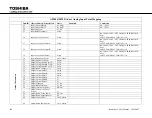
Page 262: ...SYSTEMS GROUP POWER ELECTRONICS DIVISION UPS 13131 West Little York Road Houston Texas 77041 Tel 713 466 0277 Fax 713 896 5212 US 855 803 7087 Canada 800 872 2192 www toshiba com tic industrial uninterruptible power systems ...

Reviews: