RemotEye 4 User Manual – 90988-007
25
INSTALL REMOTEYE 4 IN UPS
Follow these steps to install the RemotEye 4 card.
1.
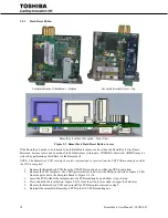
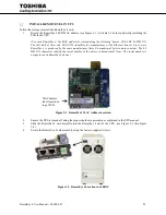
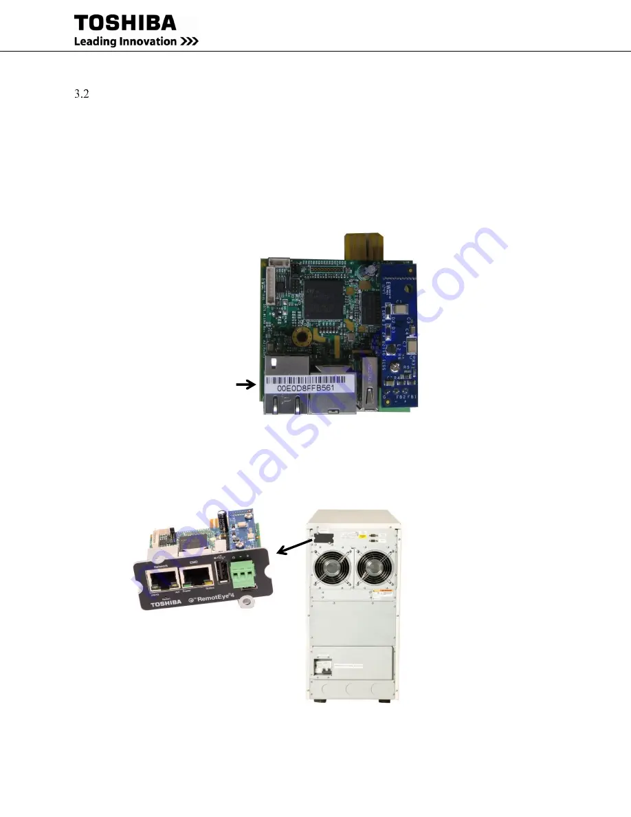
Record the RemotEye 4 PCB MAC address (see Figure 3-1 ) in Table 3-1 before physically installing the
PCB in the UPS.
(For each RemotEye 4, the MAC address is created using the following format: 00 E0 D8 LL MM NN.
The first half of this code, 00 E0 D8, identifies the manufacturer of the Ethernet board. Since every
RemotEye 4 is produced by the same manufacturer, these 3 hexadecimal bytes remain constant. The LL
MM NN characters identify the serial number of the device in hexadecimal form. The serial number is
unique for each RemotEye 4 device.)
Figure 3-1 RemotEye 4 MAC Address Location
2.
Ensure the UPS is turned off using the proper shutdown procedure as explained in the UPS manual.
3.
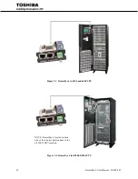
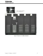
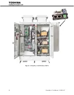
Slide the RemotEye 4 card assembly into the RemotEye 4 slot of the UPS. (see Figure 3-2 thru Figure
3-4)
4.
Secure the RemotEye 4 card assembly using the factory-supplied screws.
Figure 3-2 RemotEye 4 Location in 1600XP
MAC address
label located on
top of PCB.
Summary of Contents for RemotEye 4
Page 1: ...RemotEye 4 User Manual Document Number 90988 007 September 2018 ...
Page 4: ...4 RemotEye 4 User Manual 90988 007 This Page Intentionally Left Blank ...
Page 12: ...12 RemotEye 4 User Manual 90988 007 This Page Intentionally Left Blank ...
Page 28: ...28 RemotEye 4 User Manual 90988 007 Figure 3 6 RemotEye 4 in 5000 Series 30kVA ...
Page 97: ...RemotEye 4 User Manual 90988 007 97 Figure 11 10 VM Remote Shutdown Test ...
Page 221: ...RemotEye 4 User Manual 90988 007 221 ...
Page 261: ......

