RemotEye 4 User Manual – 90988-007
59
7.6.1
EMD Installation
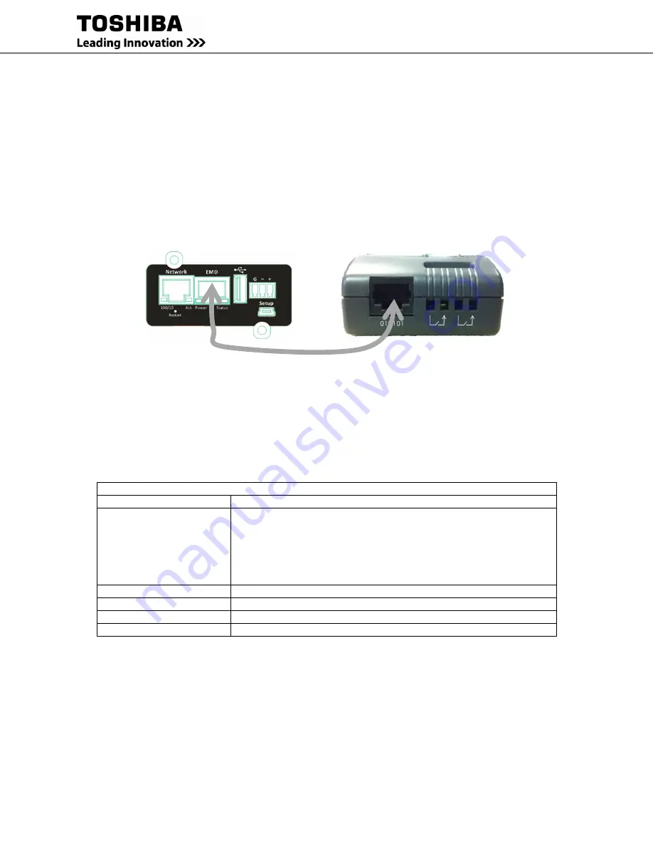
This section explains the how to setup/install the EMD to RemotEye4.
1.
Use the Cat5 (straight) cable and connect one end to the “010101” port on the EMD.
2.
Plug the other end of the Cat5 (straight) cable to the “EMD” port of the RemotEye 4.
3.
Make sure that the green “Communication Status” LED on the EMD blinks periodically. If the LED does
not blink, verify that the Cat5 cable is functional.
4.
Check the “EMD Setup” under the “EMD Configuration” page and ensure it is set to “Auto”.
5.
Go to
SETTINGS -> Interface Settings
and enable "RS-232 Interface (Enable/Disable)" and set the
"Define RS-232 Interface Protocol" to "EMD" and press the "Set" button.
Figure 7-2 EMD RemotEye 4 Installation
7.6.2
EMD Parameters
This page gives a snapshot of all EMD parameters; the parameters will be updated automatically every 5 seconds.
The text color of the parameter indicates its status based on the administrator-configurable threshold.
The list below indicates the parameter status.
Table 7-2 EMD Layout and Indicators
EMD Comprehensive View
Parameter
Value
EMD Name
(Assigned ID)
Displays the EMD Name when the EMD is connected and working
correctly.
“
Disable
” – When the EMD is connected but the “Device Status” is
Disabled in the EMD configuration settings.
“
Unknown
” – When the EMD is not connected to the RemotEye 4.
EMD Temperature (°C/°F)
(Module Temperature in °C/°F)
EMD Humidity (%)
(Relative Humidity in %)
EMD Alarm-1
Alarm 1 status: Normal/Alarm
EMD Alarm-2
Alarm 2 status: Normal/Alarm
EMD Parameter value text will be displayed in one of four colors:
GREEN: “Normal” status (Within upper and lower “Warning” limits.)
YELLOW: “Warning” status (Exceeds upper or lower “Warning” limits but within “Critical” limits.)
RED: “Critical” status (Exceeds upper or lower “Critical” limits.)
GREY: “Unknown” value (Disabled or not connected.)
The EMD provides the measurements for room (ambient) temperature, room (ambient) humidity, and two alarms
(two dry contacts). The warning/critical thresholds can be setup via the "EMD Configuration" panel.
Summary of Contents for RemotEye 4
Page 1: ...RemotEye 4 User Manual Document Number 90988 007 September 2018 ...
Page 4: ...4 RemotEye 4 User Manual 90988 007 This Page Intentionally Left Blank ...
Page 12: ...12 RemotEye 4 User Manual 90988 007 This Page Intentionally Left Blank ...
Page 28: ...28 RemotEye 4 User Manual 90988 007 Figure 3 6 RemotEye 4 in 5000 Series 30kVA ...
Page 97: ...RemotEye 4 User Manual 90988 007 97 Figure 11 10 VM Remote Shutdown Test ...
Page 221: ...RemotEye 4 User Manual 90988 007 221 ...
Page 261: ......


