background image

E6581277

c


- 2 -

„

 Limitation of use

Safety precaution

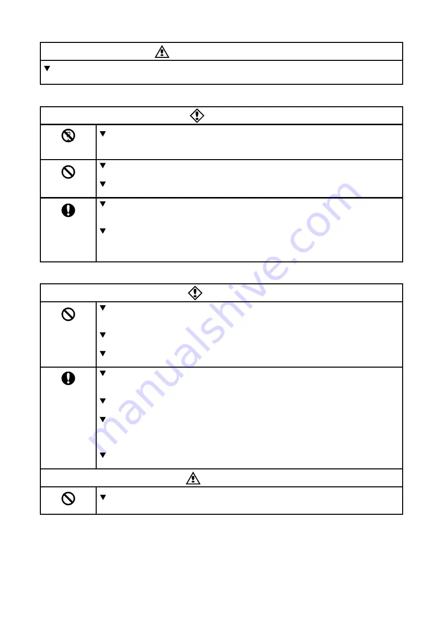
  Never use this unit with any device other than TOSVERT series inverters. Doing so may cause an

accident.

„

 Handling in general

Danger

Never

Disassemble

Never disassemble, modify or repair the product.
Disassembling the product may cause electric shocks, fire or injuries.
For repairs, call your sales/repair agency.

Prohibited

Do not put or insert foreign objects such as waste cable, bars, or wires into the product.
It may lead to electric shocks or fire.
Do not splash water over the product, and do not wipe the body with a wet cloth.
It may lead to electric shocks or fire.

Mandatory

Turn off input power before wiring.
Wait at least 15 minutes and check to make sure that the charge lamp (on the inverter
unit) is no longer lit.
Turn off the power immediately in case of any abnormalities such as smoke, smell or
abnormal noise.
Neglect of these conditions may lead to fire.
For repairs, call your sales/repair agency.

„

 Transportation and installation


Danger

Prohibited

Do not install or operate the inverter if it is damaged or any part of it is missing.
Operating a defective inverter may lead to electric shocks or fire.
For repairs, call your sales/repair agency.
Do not put any flammable material near the product.
It may catch fire due to the product sparking in the case of a malfunction.
Do not connect a LAN cable or telephone modular cable to Remote Keypad. Doing so
may cause a failure or accident.

Mandatory

E

lectrical construction work must be done by a qualified expert.

Connection of input power by someone who does not have expert knowledge may
result in fire or electric shock.
Operate under the environmental conditions prescribed in the instruction manual.
Operations under any other conditions may result in malfunction.
An emergency stop device must be installed that fits with system specifications
  (e.g. shut off input power then engage mechanical brake).
Operation cannot be stopped immediately by the inverter or Remote Keypad alone, thus
risking an accident or injury.
Use the Toshiba-specified cable for connecting this optional unit. (Refer to page 4.)
The use of any other option may result in an accident.

Warning

Prohibited

Do not install the product in any place subject to vibrations or it may fall.    
This may lead to the product falling and causing injury.

Summary of Contents for RKP002Z

Page 1: ... delivered to the end user of Remote Keypad 2 Read this manual before installing or operating the Remote Keypad Keep it in a safe place for reference 3 All information contained in this manual are subject to change without notice Please confirm the latest information on our web site www inverter co jp ...

Page 2: ...o injury 1 to people or that these errors may cause damage to physical property 2 1 Such things as injury burns or shock that will not require hospitalization or long periods of outpatient treatment 2 Physical property damage refers to wide ranging damage to assets and materials Meanings of symbols Marking Meaning of marking Indicates prohibition Do not do it What is prohibited will be described i...

Page 3: ...damaged or any part of it is missing Operating a defective inverter may lead to electric shocks or fire For repairs call your sales repair agency Do not put any flammable material near the product It may catch fire due to the product sparking in the case of a malfunction Do not connect a LAN cable or telephone modular cable to Remote Keypad Doing so may cause a failure or accident Mandatory Electr...

Page 4: ...ectors and Transporters or Industrial Waste Disposal Persons If the collection transport and disposal of industrial waste is done by someone who is not licensed for that job it is a punishable violation of the law Laws in regard to cleaning and processing of waste materials Notes on operation Notes Avoid installing in a place where ambient temperature or and humidity change sharply Keep the transm...

Page 5: ...al please keep it handy for future reference Part numbering RKP 002 Z 1 Revision number Cable length Z means without cable Model number of Remote Keypad 002 standard Symbol of Remote Keypad Accessory check list Remote Keypad is shipped together with the following accessories On opening the packing case check to see if the following accessories are contained or not 1 Instruction manual 1 copy Engli...

Page 6: ...1 Copying function copy 10 4 3 2 Simple copying function 11 4 3 3 Comparing function comp 12 4 3 4 Memory protection function prot 13 4 3 5 Memory initializing function clr 14 4 3 6 Remote Keypad parameter editing function 15 5 Before making a service call 16 5 1 Error message 16 5 2 Procedure to reset Remote Keypad 16 5 3 Warning indications 17 5 4 Other problems 17 6 Outline drawing 18 7 Specifi...

Page 7: ...ored in one of Remote Keypad s memory can be compared with the data of inverter s memory In addition data stored within any of the 3 Remote keypad memories A B or C can be compared with each other 5 Memory protecting function Data written on the inverter s memory and the memories of Remote Keypad are protected by this function to protect against data damage 6 Memory initializing function One of th...

Page 8: ...s when the Remote Keypad is in COPYMODE RUN key lamp Lights when RUN key is enabled Up Down key lamp Frequency setting by up down keys are enabled while this lamp is lit EASY lamp 2 Lights when the inverter is in EASY mode Potentiometer lamp 3 Lights when the potentiometer is enabled Potentiometer 3 Operation frequency can be changed when the built in potentiometer lamp is lit SFT C Display Displa...

Page 9: ...ote Keypad with the inverter according to the procedure stated below 1 Set Communication Mode Switch refer to page 7 on the reverse side of Remote Keypad The position varies for the inverter series RS485 The inverter with RS485 2 wire type port ex VF AS1 etc LOGIC The inverter with Common Serial Port ex VF S11 VF nC1 VF S9 VF A7 VF P7 2 Set communication baud rate the inverter parameter f800 to 96...

Page 10: ...hrough the inverter s control panel However if Remote Keypad is deactivated by an unexpected event such as an abnormality the inverter s input keys remain functional 4 3 COPY MODE In COPY MODE storing and loading the parameters are permitted Editing the parameters is not permitted Key LED indication Key operation and description chc init c0py When COPY MODE is initiated chc is shown in the display...

Page 11: ...rom inverter memory to memory A in b copying data from inverter memory to memory B in c copying data from inverter memory to memory C and to in a again in this order If the memory A B or C is selected as to copy data from the display changes accordingly example shown in parentheses for memory A ENT in a f_ _ _ Executing copy function After selecting the memory to copy to Example in a select memory...

Page 12: ... the memory to copy from to inverter Example select a in press the ENT key and start copying Then the display shows f_ _ _ This is the parameter title of the parameter being copied now If Remote Keypad is unable to copy the selected parameter the display shows the parameter title flashing in the display window To continue copying press ENT key c0mp end _ _ _ _ 4 digits Completion of copying functi...

Page 13: ...key is pressed the display changes as follow in a comparing data between inverter memory and memory A in b comparing data between inverter memory and memory B in c comparing data between inverter memory and memory C and to in a again in this order If for example memory A is selected instead of in different indication appears as shown in parentheses ENT in a flashing Entering the selected memory to...

Page 14: ...ey press the ENT key and the display shows the present memory protection status When on appears on the display the selected memory is protected When off appears on the display the selected memory is not protected SFT off on off Protecting the selected memory Each time the SFT key is pressed the indication in the display changes on protecting the selected memory write prohibited off canceling prote...

Page 15: ...to default setting and to a again in this order ENT a off Entering the memory to initialize After selecting a memory for initialization selecting memory A by way of example with the SFT key press the ENT key and off appears in the display window SFT off on off Initializing the selected memory Each time the SFT key is pressed the display changes on to initialize selected memory off not to initializ...

Page 16: ...r display Each time the SFT key is pressed the display changes f 01 Software version displaying f 02 Automatic comparing function alternately ENT f 02 1 f 01 v100 Entering a parameter title to edit or display If f 02 is selected with the SFT key and the ENT key is pressed the current value 1 Executing comparison after copying by way of example appears in the display window If f 01 is selected as p...

Page 17: ...needs to be repaired N B In REMOTE KEYPAD MODE this is only alarm displaying The operation keys are also effective while the display is showing this alarm message eePe EEPROM built in Remote Keypad is abnormal If the same indication appears after writing data again it needs to be repaired coMe Abnormal communication Check the connection of the inverter s serial communication cable Communication Mo...

Page 18: ...parison function or that can not be written while using the copying function Press the ENT key to continue the ESC key to cancel When Remote Keypad did not find any data in one memory it flashes in case the data is missing in the memory that was selected first or Hz if it is missing in the memory that was selected second This may happen parameter data may be missing when the software versions of t...

Page 19: ...E6581277c 18 6 Outline drawing Following is the outline drawing of Remote Keypad Unit mm ...

Page 20: ...front of the panel board cut the area shown below for mounting Remote Keypad Then fix Remote Keypad on the panel board with the mounting screws M3 x 12 supplied as accessories M3 screw tightening torque 0 6 Nּm Unit mm The front view of the panel board 63 0 16 4 10 4 4 φ4 0 hole 4 6 35 9 98 0 Upper side ...

Page 21: ...f cooling 8 Warranty Any part of the unit that is proved to be defective will be repaired free of charge under the following conditions 1 This product will be repaired free of charge if problem fault occurs under normal handling within one year of delivery and is caused obviously by a design or manufacturing defect 2 The warranty applies only to the delivered unit 3 For the following kinds of fail...

Reviews: