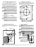
background image

E6581323

LCD Remote Keypad

 Instruction Manual

RKP004Z-0

Notice

1. Please see to it that this instruction manual reaches the actual user of the LCD remote

keypad without fail.

2. Be sure to read this instruction manual carefully before installing and using the LCD remote

keypad. After reading the manual, be sure to store it.

Summary of Contents for RKP004Z-0

Page 1: ...ice 1 Please see to it that this instruction manual reaches the actual user of the LCD remote keypad without fail 2 Be sure to read this instruction manual carefully before installing and using the LCD remote keypad After reading the manual be sure to store it ...

Page 2: ......

Page 3: ...ish This instruction manual mainly explains how to use the keys on the LCD remote keypad For details of parameters available refer to the instruction manual included with your inverter Danger Prohibited Never connect the unit to any inverter other than a VF AS1 series inverter or any communications device Do not use any cable other than an optional interconnect cable designed specifically for the ...

Page 4: ...BP006Z Interconnect cable CAB0075 5m IP65 attachment SBP007Z You can install the LCD remote keypad to the inverter or operate the inverter by remote control combining optional products For details refer to 2 Installing the LCD remote keypad Installation on an inverter no optional products required RKP 004Z Installation on a board RKP 004Z SBP006Z CAB007 Installation on a board protective structure...

Page 5: ...ibited Never disassemble modify or repair This can result in electric shock fire and injury For repairs call your sales agency Prohibited Don t place or insert any kind of object into the inverter electrical wire cuttings rods wires This can result in electric shock or fire Do not allow water or any other fluid to come in contact with the inverter This can result in electric shock or fire Do not u...

Page 6: ... of industrial waste is done by someone who is not licensed for that job it is a punishable violation of the law Laws in regard to cleaning and processing of waste materials Persons who specialize in the processing of waste and known as industrial waste product collectors and transporters or industrial waste disposal persons Notes on use Notes Insert a magnetic contactor or a similar device betwee...

Page 7: ... 2 Using an EASY key function 5 2 5 3 Selecting a language to be displayed 5 3 5 4 Performing jog run 5 4 5 5 Emergency stop reset operation 5 4 6 Operation in Parameter Setup Mode 6 1 6 1 Searching for the change histories of parameters History function 6 1 6 2 Setting a basic parameter 6 2 6 3 Setting an extended parameter 6 3 6 4 Searching for parameters whose settings were changed Search for c...

Page 8: ...3 STOP RESET key Stops operation To use this key parameter settings need to be changed Refer to page 1 3 In case the inverter has tripped pressing this key twice in a row resets the inverter If multiple commands are entered by pressing the three keys F2 F3 and F4 or ESC FWD and RUN in rapid succession a stop command will be issued instead to stop operation Control dial ENTER key 1 In a menu window...

Page 9: ...e While the frequency is set at 0Hz the RUN key is pressed EOFF blinking Waiting for emergency stop operation Displays the title or status of the window Displays settings both in a menu form and numerically or a list of various kinds of information Displays the function assigned to each function key in an abbreviation or graphical symbol The abbreviations and graphical symbols in the window corres...

Page 10: ...ameter settings need to be changed as described below Parameter CMOd Command input mode 1 Pane LCD option Parameter FMOd Frequency input mode 1 4 Pane LCD option Parameter Fr Panel Fwd Rvs selection 2 Forward switchable 3 Reverse switchable This change of parameter settings makes it possible to start operation using the RUN key to stop operation using the STOP RESET key and to switch between forwa...

Page 11: ...and then follow these steps 1 Remove the serial RS485 port cover from the inverter s main operation panel To detach the cover wrench it open using a flat blade screwdriver or any other flat tipped tool 2 Mount the remote keypad on the inverter s main operation panel Insert the connector on the remote keypad into the RS485 port while pushing in the lock knobs and then release the lock knobs to secu...

Page 12: ...n optional interconnect cable designed specifically for the unit Failure to observe this might cause the unit to break down and result in an electric shook or fire Turn off the inverter as shown in the figure below 115 104 5 5 5 5 4 Φ3 5 100 114 5 5 Make a hole in the board as shown in the figure below IP54 attachment optional Dedicated interconnect cable optional The pin configuration of the dedi...

Page 13: ...munications device Do not use any cable other than an optional interconnect cable designed specifically for the unit Failure to observe this might cause the unit to break down and result in an electric shook or fire Turn off the inverter as shown in the figure below The pin configuration of the dedicated interconnect cable is different from that of any other commercially available cable Therefore ...

Page 14: ...the unit is turned on for the first time after purchase 2 Select confirm the desired language using the control dial In this example English is selected There is no need to select confirm the language 3 The Startup window is displayed and soon replaced by the top window of Top View Mode Top View Mode Fwd 0 0Hz STOP 0 0Hz Lng Quick Language selection English 日本語 インバータ パネル CONNECTION IN PROGRESS V1 ...

Page 15: ... statuses and information such as the operating status of the inverter and information on the terminal board Refer to 7 Operation in Status Monitor Mode The figures below show the top windows of these modes To change from one mode to another press the ESC key When Quick mode is selected with the EASY key other windows are displayed Parameter Setup Mode Parameter Setup Mode Category Selection Top M...

Page 16: ...ou to the Language selection window 5 1 Setting a panel operation frequency When Frequency input mode1 parameter FMOd 4 as a frequency setting mode an operation frequency can be set with the remote keypad 1 Press the control dial The panel frequency window appears The current operation frequency setting is displayed at the center of the window The current output frequency is displayed in the upper...

Page 17: ...mode and Standard Setting mode parameter F750 0 Panel Function of switching between Operation Panel and Remote parameter F750 2 Update Function of updating the Peak Minimum Hold setting parameter F750 3 The shortcut key function parameter F750 1 cannot be used Even if the parameter is so set the name of the function is not displayed on the screen Function of switching between Quick mode and Standa...

Page 18: ...is no need to switch to Panel Operation mode by changing parameter settings The switching between operation modes cannot be done during operation Peak Minimum Hold setting 1 Update is displayed If the F1 key is not pressed 2 The instant the F1 key is pressed in this situation a measurement for peak hold minimum hold starts When the F1 key is pressed is displayed in reverse video If the F1 key is p...

Page 19: ...leased Functions of function keys F1 key Switches between Quick mode and Standard Setting mode F2 key Brings you to the Language selection window F4 key Executes a jog run command 5 5 Emergency stop reset operation To make an emergency stop or to reset the inverter follow these steps An emergency stop can be made when operation is performed with the terminal board parameter CMOd 0 2 3 or 4 1 Press...

Page 20: ...en press the STOP RESET key again The Trip window appears and the blinking code CLr is displayed in it 4 Last of all press the STOP RESET key once again to reset the inverter Top View Mode Fwd 60 0 Hz Trip CLr Trip reset STOP Key Lng Quick ...

Page 21: ...hange histories of up to 5 parameters can also be displayed in a list form in order of novelty 1 Select confirm History function using the control dial Change histories are displayed in a list form in order of novelty If the number of change histories exceed 5 change histories except the 5 latest ones are deleted in the order in which changes were made Functions of function keys F1 key Brings you ...

Page 22: ...ected is changed by specifying a value the value specified is displayed In addition the minimum allowable value min and the maximum allowable value max are also displayed at the bottom of the window Functions of function keys The functions keys allow you to select the position or decimal place of each figure operation frequency you want to increment or decrement with the control dial F1 key Select...

Page 23: ...splayed decrements each time this key is pressed F2 key Displays the previous window F3 key Displays the next window F4 key Displays parameters in the number range of 200 The number displayed increments each time this key is pressed 2 Change the parameter setting To do this perform steps 2 and 3 in the 6 2 Setting a basic parameter section If the setting selected is changed by specifying a value B...

Page 24: ...setting were changed 2 Search for the desired parameter by pressing the F3 or F4 key repeatedly The title function and current setting of the parameter selected are displayed Functions of function keys F1 key Brings you to the Top View Mode F3 key Displays in reverse order parameters whose setting were changed F4 key Displays in normal order parameters whose setting were changed In this window set...

Page 25: ...d Set value and current value of parameter F716 Inverter overload Set value and current value of parameter F717 Motor over load Set value and current value of parameter F718 Input terminal 1 S4 S3 R F Input terminal board information Standard terminal board Input terminal 2 L8 L7 L1 Input terminal board information Optional terminal board Output terminal 1 FL OUT2 Output terminal board information...

Page 26: ...bottom of the window Type of window 2 Displays information in a graph form This type of window displays input output terminal information and a life alarm in a graph form Ex Input terminal S4 S3 R F It displays the ON OFF status of each terminal signal and the ON OFF status of an alarm signal in a graph form If the arrow is moved to a terminal or alarm symbol the name of the function assigned to t...

Page 27: ...onds Check whether the key operates normally If it does not operate normally it has to be repaired Operation cannot be controlled with the RUN key or the STOP RESET key Panel Operation mode is not enabled The operation frequency is set at 0 0Hz Change the setting of the basic parameter COMd command input mode to 1 panel LCD option Set an operation frequency according to the setting of the basic pa...

Page 28: ...ll not be exposed to direct sunlight corrosive or explosive gases vapor coarse particulates including dust and where there is no grinding fluid or grinding oil nearby Ambient temperature 10 to 60 C Storage temperature 25 to 65 C Relative humidity 20 to 93 no condensation and absence of vapor Vibration 5 9m s2 0 6G or less 10 to 55Hz compliant with JIS C 60068 2 6 Cooling method Self cooling Outsid...

Page 29: ...r the following kinds of failure or damage the repair cost shall be borne by the customer even within the warranty period 1 Failure or damage caused by misuse or unauthorized repairs or modification 2 Failure or damage caused by the drop of the product after purchase or rough handling during transportation 3 Failure or damage caused by fire salty water or wind corrosive gas earthquake storm or flo...

Page 30: ......

Page 31: ......

Page 32: ...E6581322 ...

Reviews: