7.
Feature Description
(1)
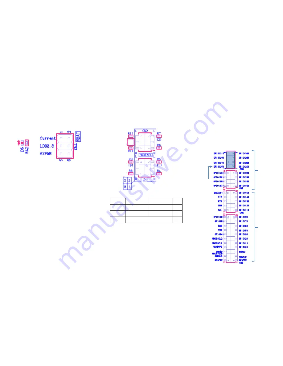
Power Select Pin(CN4)
Use this pin header when selecting the power supply for the
Bluetooth LE IC.
And measuring the current consumption of the Bluetooth LE IC.
.
NOTE1 (Selecting Power Supply)
When using external power supply, be sure to open 3-4 pin to
avoid collision with LDO output.
NOTE2(Current measurement)
By connecting an ammeter to 1-2 pin, it is possible to measure
consumption current of Bluetooth LE IC alone. .
(2) Mode Select (CN1-2)
Depending on the mounting of the jumper socket, you can switch
between HCI mode and User-App mode. Since the mode is
confirmed immediately after releasing reset, you can use it in any
state after booting.
User-App Mode
HCI Mode
GPIO 1
H or Open
L
CN1
GPIO 2
Don’t care
L
CN2
GPIO B
Don’t care
H or Open
CN1
(3) I/O Pin Header (CN5-8)
To this pin header
・
Reset input of Bluetooth LE IC
・
SWD interface
・
All GPIOs of each IC are connected
Since no other circuit is connected between IC and pin header, it
can contact directly with IC terminal. CN8 is not mounted. If you
use GPIO24-31, you need to install a pin header to CN8.
G
PI
O
1
G
PI
O
2
G
PI
O
B
Re
se
rv
e
Q
FN 4
0pi
n
/ Q
FN6
0 p
in
co
m
m
on
Q
FN60
pi
n
onl
y
Q
FN 4
0pi
n
/ Q
FN60
p
in
co
m
m
on
No
M
ou
nt


