

100CS
1-1
1.1 Features
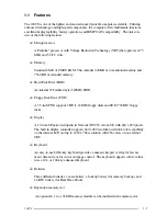
The 100CS is one of the lightest and most advanced portable computers available. Utilizing
advanced technology and high-speed components, the computer offers multimedia functions,
excellent display legibility, battery operation, and IBM PC/AT compatibility. The unit con-
sists of the following features:
❑
Microprocessor
A Pentium
®
processor with Voltage Reduction Technology (VRT) that operates at 75
MHz and 3.3/2.9 volts.
❑
Memory
Standard 8 MB of CMOS RAM. This includes 640 KB of conventional memory and
7360 KB of extended memory.
❑
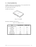
Hard Disk Drive (HDD)
An internal 528 million byte (520MB) HDD.
❑
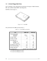
Floppy Disk Drive (FDD)
A 3.5-inch FDD supports 2HD (1.44 MB) floppy disks and 2DD (720 KB) floppy
disks.
❑
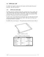
Display
A 10.4-inch Dual-scan Supertwist Nematic (DSTN) color LCD with 640 x 480 pixels.
The built-in display controller supports 640 x 480 resolution with 64k colors capability
on the internal LCD and up to 1024 x 768 resolution with 256 colors on an external
CRT.
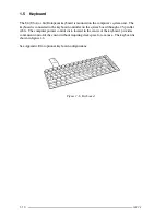
❑
Keyboard
An easy-to-use 82/84-key keyboard provides a numeric keypad overlay for fast nu-
meric data entry or for cursor and page control. The keyboard supports software that
uses a 101- or 102-key enhanced keyboard.
❑
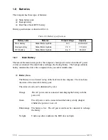
Batteries
Three different batteries: a main battery, a backup battery (for memory backup), and
an RTC battery (for Real Time Clock).
❑
Expansion memory slot
An optional 8, 16, or 32 MB memory module can be installed in the memory slot.


