background image

User's Manual

i

Version   

8

   Last Saved on 18/09/99 14:07

Satellite 2610/2650 User's Manual  – 0000IMPR.DOC – ENGLISH – Printed on 18/09/99 as IM_261UK

 2610/2650 Series

Portable Personal Computer
User’s Manual

Summary of Contents for SATELLITE 2610 Series

Page 1: ...User s Manual i 2610 2650 Series Portable Personal Computer User s Manual ...

Page 2: ...als are subject to change without notice Toshiba assumes no liability for damages incurred directly or indirectly from errors omissions or discrepancies between the computer and the manual Trademarks IBM is a registered trademark and IBM PC OS 2 and PS 2 are trademarks of International Business Machines Corporation Intel is a registered trademark and Celeron is a trademark of Intel Corporation MS ...

Page 3: ...ng the YMark2000 test under NSTL s self testing program and meets the NSTL test standards for Year 2000 hardware compliance NSTL makes no recommendation or endorsement of any product This test data report was prepared by Toshiba using licensed testing products from NSTL NSTL MAKES NO WARRANTIES EXPRESS OR IMPLIED AS TO RESULTS TO BE OBTAINED BY ANY PERSON OR ENTITY FROM USE OF THE SERVICES OR THE ...

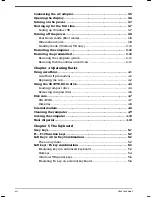
Page 4: ...iv User s Manual ...

Page 5: ...FACTURER TO COMPLY WITH DHHS RULES 21 CFR SUBCHAPTER J APPLICABLE AT THE DATE OF MANUFACTURE MANUFACTURED TOSHIBA CORPORATION 1 1 SHIBAURA 1 CHOME MINATO KU TOKYO 105 8001 JAPAN CAUTION This appliance contains a laser system and is classified as a CLASS 1 LASER PRODUCT To use this model properly read the instruction manual carefully and keep this manual for your future reference In case of any tro...

Page 6: ...DHHS RULES 21 CFR CHAPTER 1 SUBCHAPTER J APPLICABLE AT DATE OF MANUFACTURE CLASS 1 LASER PRODUCT LASER KLASSE 1 TEAC CORPORATION 3 7 3 NAKA CHO MUSASHINO SHI TOKYO JAPAN EN60825 1 94 CAUTION This appliance contains a laser system and is classified as a CLASS 1 LASER PRODUCT To use this model properly read the instruction manual carefully and keep this manual for your future reference In case of an...

Page 7: ...NUFACTURER TO COMPLY WITH DHHS RULES 21 CFR SUBCHAPTER J APPLICABLE AT THE DATE OF MANUFACTURE MANUFACTURED TOSHIBA CORPORATION 1 1 SHIBAURA 1 CHOME MINATO KU TOKYO 105 8001 JAPAN CAUTION This appliance contains a laser system and is classified as a CLASS 1 LASER PRODUCT To use this model properly read the instruction manual carefully and keep this manual for your future reference In case of any t...

Page 8: ...ouch prolonged physical contact may result in a temporary heat imprint on the skin It is recommended that prolonged physical contact is avoided Also if the computer has been used for a long time avoid direct contact with the metal plate supporting the I O ports It can become hot Mobile phones Use of mobile phones can interfere with the PC sound system The PC operation is not impaired but it is rec...

Page 9: ...t industry environments For example the following environments are not approved Industrial Environments environments with a mains voltage 230V Medical Environments Automotive Environments Aircraft Environments If this product is supplied with a network port please refer to the paragraph Network connection Any consequences resulting from the use of this product in working environments that are not ...

Page 10: ...l operation on every PSTN network termination point In the event of problems you should contact your equipment supplier in the first instance Network Compatibility Statement This product is designed to work with and is compatible with the following networks It has been tested to and found to conform with the additional requirements contained in EG 201 121 Germany ATAAB AN005 AN006 AN007 AN009 AN01...

Page 11: ...l features 1 6 Options 1 9 Chapter 2 The Grand Tour Front with the display closed 2 1 Left side 2 3 Right side 2 4 Back side 2 5 Underside 2 6 Front with the display open 2 7 Indicators 2 9 Drives 2 11 3 diskette drive 2 11 CD ROM drive 2610CDT 2 12 DVD ROM drive 2650XDVD 2 13 AC adaptor 2 15 Chapter 3 Getting Started Setting up 3 1 General conditions 3 2 Placement of computer 3 2 Seating and post...

Page 12: ...ivers 3 12 Chapter 4 Operating Basics Using AccuPoint 4 1 AccuPoint II precautions 4 2 Replacing the cap 4 2 Using the CD DVD ROM drive 4 3 Loading compact discs 4 3 Removing compact discs 4 6 Disk care 4 7 CDs DVDs 4 7 Diskettes 4 8 Internal modem 4 8 Cleaning the computer 4 9 Moving the computer 4 10 Heat dispersal 4 10 Chapter 5 The Keyboard Grey keys 5 1 F1 F12 function keys 5 2 Soft Keys Alt ...

Page 13: ... types 6 4 Battery pack 6 4 Real Time Clock battery 6 4 Care and use of the battery pack 6 5 Safety precautions 6 5 Charging the batteries 6 6 Monitoring battery capacity 6 7 Maximising battery operating time 6 7 Retaining data with power off 6 8 Extending battery life 6 8 Replacing the battery pack 6 8 Removing the battery pack 6 8 Installing the battery pack 6 10 Starting the computer by passwor...

Page 14: ...SETUP 8 16 Executing TSETUP 8 16 Changing values in the TSETUP menu 8 17 Accepting changes and exiting SYSTEM SETUP 8 17 Default configuration 8 17 TSETUP options 8 18 Memory 8 18 Password 8 18 Battery 8 18 Password security 8 26 How to set the passwords 8 27 How to reset the passwords 8 29 Enabling Hardware Setup and TSETUP access in user password mode 8 31 Making a password service diskette 8 32...

Page 15: ...lf test 10 3 Power 10 4 Password 10 6 Hotkeys 10 6 Keyboard 10 6 LCD panel 10 7 Hard disk drive 10 8 CD ROM drive 10 9 DVD ROM drive 10 10 Diskette drive 10 11 Printer 10 11 Pointing device 10 12 PC card 10 13 Monitor 10 14 Sound system 10 14 USB 10 15 Hibernation 10 15 Modem 10 16 Diagnostic test 10 17 Executing the diagnostic test program 10 17 Choosing test options 10 18 Test sequence 10 19 Sub...

Page 16: ...ns Appendix B AC Power Cord and Connectors Appendix C The Toshiba International Warranty Appendix D Keyboard Layouts Appendix E Display Controller and Modes Appendix F If your computer is stolen Appendix G ASCII Character Codes Glossary Index ...

Page 17: ...er If you are an experienced computer user please continue reading the preface to learn how this manual is organised then become acquainted with this manual by browsing through its pages Be sure to look over the Special features section of the Introduction to learn about features that are uncommon or unique to the computers and carefully read Setup and Password Security Manual contents This manual...

Page 18: ... be working properly The Appendices provide technical information about your computer The Glossary defines general computer terminology and includes a list of acronyms used in the text The Index quickly directs you to the information contained in this manual Conventions This manual uses the following formats to describe identify and highlight terms and operating procedures Abbreviations On first a...

Page 19: ...e face you see to the left Text you are to type in is usually preceded by the keyboard icon Display ABC Names of windows or icons or text generated by the computer that appears on its display screen is presented in the type face you see to the left Text generated by the computer is usually preceded by the screen icon Messages Messages are used in this manual to bring important information to your ...

Page 20: ... Series Portable Personal Computer Universal AC adaptor and power cord TV adaptor cable 2650XDVD only The following software is pre installed on the hard disk Microsoft Windows 98 Second Edition Microsoft Works 4 5 Windows Utilities Display Driver for Windows Sound Driver for Windows Modem driver DVD Driver 2650XDVD DVD Video Player 2650XDVD Online User s Manual Online International Modem User s M...

Page 21: ...ay The computer s LCD panel supports high resolution video graphics It employ s an AGP Accelerated Graphics Port bus for superior video and 3 D performance The screens can be set at a wide range of viewing angles for maximum comfort and readability The display controller also supports simultaneous display on the internal LCD and on an external monitor The following displays are available 2610CDT 1...

Page 22: ...the secondary mouse button The computer s keyboard supports software that uses a 101 or 102 key enhanced keyboard See Chapter 5 The Keyboard for details HDD The computer has a 6 0 billion byte integrated 2 hard disk drive for nonvolatile storage of data and software Diskette drive A 3 diskette drive accommodates both 1 44 MB double sided high density double track 2HD and 720 KB double sided double...

Page 23: ...speed data transfer Universal Serial Bus port A Universal Serial Bus USB port enables chain connection of a number of USB equipped devices to one port on your computer For example you might connect a USB HUB to the computer then connect a keyboard to the USB HUB and a mouse to the keyboard Use the USB drivers that come with USB devices External monitor port The female 15 pin D shell connector lets...

Page 24: ...II This pointer control stick located in the centre of the keyboard provides convenient control of the cursor without requiring desk space for a mouse Control buttons include primary secondary and two scroll buttons Plug and Play When you connect an external device to the computer Plug and Play capability enables the system to recognise the connection and make the necessary configurations automati...

Page 25: ...r item of the Power Save Mode window in Power Saver HDD automatic power off This feature automatically cuts off power to the hard disk drive when it is not accessed for a time specified Power is restored when the hard disk is accessed You can specify the time in the Turn off hard disks item of the Power Saver Utility System automatic shut down This feature automatically shuts down the system when ...

Page 26: ...end This feature turns power to the computer off when the display panel is closed You can specify the setting in the When I close the lid item of the System Power Mode window in Power Saver Auto power on This feature lets you set a time and date for the computer to turn on automatically The feature is useful for receiving remote communications while you are asleep or away You can specify the setti...

Page 27: ...r the following conditions You are using DriveSpace or other compression utility You are using Windows 98 drive converter to convert drives to the File Allocation Table 32 format Standby Windows 98 only In Standby mode power to the system remains on but the CPU and all other devices are in sleep mode When the computer is in standby mode the Power LED glows orange To enter Standby mode click Start ...

Page 28: ... your Toshiba dealer Use it as a spare or replacement AC adaptor If you use your computer at more than one site frequently it may be convenient to purchase an additional AC adaptor for each site so you will not have to carry the adaptor with you Keytop sets You can customise your keyboard for a variety of languages by replacing the keytops Battery charger The battery charger lets you charge extra ...

Page 29: ... BUTTON DISPLAY LATCH CD ROM OR DVD ROM DRIVE SYSTEM INDICATORS DISKETTE DRIVE Diskette drive This drive lets you use both 1 44 MB double sided high density double track 2HD and 720 KB double sided double density double track 2DD disks System indicators The system indicators provide icons for monitoring the status of DC IN Power Battery Built in HDD and Diskette CD ROM or DVD ROM drive Details are...

Page 30: ... the left and hold it briefly to toggle power to the CD DVD ROM drive on or off When you release the button it will return to its original position You can access this button even when the panel is closed to use the CD DVD ROM drive as an audio player If no control button is activated within four minutes of turning on the CD DVD ROM drive power power to the drive will automatically be turned off I...

Page 31: ... button lock Set this lock to the locked position to prevent inadvertent power on or power off RESET Reset Press the reset button to reset the computer when it does not respond to keyboard commands Use a narrow object such as the tip of a covered ball point pen The system restarts clearing all data in memory Do not use a pencil to push the reset button Pencil lead can break off inside the computer...

Page 32: ... s circuitry Volume control Use this dial to adjust the volume of the stereo speakers Headphone jack A standard 3 5 mm mini headphone jack enables connection of a stereo headphone 16 ohm minimum or other device for audio output When you connect headphones the internal speaker is automatically disabled Microphone jack A standard 3 5 mm mini microphone jack enables connection of a monaural microphon...

Page 33: ...ck panel COOLING VENTS DC IN 15V PS 2 MOUSE KEYBOARD PORT SERIAL PORT EXTERNAL MONITOR PORT PARALLEL PORT USB PORT The back side of the computer Universal Serial Bus port A plastic cover protects the Universal Serial Bus USB port which enables chain connection of a number of USB equipped devices to one port on your computer For example you might connect a USB HUB to the computer then connect a key...

Page 34: ... turn on the power DC IN 15V DC IN 15V The AC adaptor s DC output plug connects to this socket Use only the model of AC adaptor that comes with the computer Using the wrong adaptor can damage your computer Underside This figure shows the underside of the computer Make sure the display is closed before turning over your computer BATTERY COVER BATTERY LATCH The underside of the computer Battery cove...

Page 35: ... BUTTON STEREO SPEAKER RIGHT SCROLL BUTTONS ACCUPOINT II CONTROL BUTTONS ACCUPOINT II STEREO SPEAKER LEFT The front with the display open Display screen The LCD displays high contrast text and graphics The computer s LCD consists of up to 800 x 600 2610CDT pixels or 1024 x 768 2650XDVD pixels or dots Refer to Appendix E When the computer operates on the AC adaptor the display screen s image will b...

Page 36: ...nd launch the browser automatically in one step Stereo speakers The speakers emit sound generated by your software as well as audio alarms such as low battery condition generated by the system AccuPoint II A pointer control device located in the centre of the keyboard is used to control the on screen pointer Refer to the Using AccuPoint II section in Chapter 4 Operating Basics AccuPoint II control...

Page 37: ... This icon glows green when the alphabet keys are locked in uppercase Arrow mode When the Arrow mode icon lights green you can use the keypad overlay light grey labelled keys as cursor keys Refer to the Keypad overlay section in Chapter 5 The Keyboard Numeric mode You can use the keypad overlay light grey labelled keys for numeric input when the Numeric mode icon lights green Refer to the Keypad o...

Page 38: ...e computer is on In Windows 98 if you select Standby from the Shut Down menu this indicator glows orange Battery The Battery indicator indicates the condition of the battery s charge Green indicates full charge orange indicates battery charging and flashing orange indicates a low battery charge Refer to Chapter 6 Power and Power Up Modes Built in HDD This indicator glows green when the computer is...

Page 39: ...e Disk In Use Indicator This indicator lights when the diskette is being accessed Diskette slot Insert diskettes in this slot Eject button When a diskette is fully seated in the drive the eject button pops out To remove a diskette push in the eject button and the diskette pops out partially for easy removal Check the disk in use indicator when you use the diskette drive Do not press the eject butt...

Page 40: ...CD EXTRA CD ROM CD R read only Photo CD CD Rewritable read only Video CD CD I Video Eject button Press the eject button to open the drawer partially CD In Use Indicator This indicator lights when the CD is being accessed Eject hole Insert a slender object to open the drawer when the power to the computer is off Check the CD in use indicator when you use the CD ROM drive Do not press the eject butt...

Page 41: ...centre and maximum outer edge for DVDs and CDs are DVD 1 7 speed centre 4 speed outer edge CD 10 3 speed centre 24 speed outer edge This drive supports the following formats Audio CD CD I Video DVD ROM DVD Video CD ROM CD EXTRA Photo CD CD R read only Video CD CD Rewritable read only DVD In Use Indicator This indicator lights when a CD DVD is being accessed Eject button Press the eject button to o...

Page 42: ... When you purchase DVD media make sure it matches your drive otherwise it will not play properly Code Region 1 Canada United States 2 Japan Europe South Africa Middle East 3 Southeast Asia East Asia 4 Australia New Zealand Pacific Islands Central America South America Caribbean 5 Russia Indian Subcontinent Africa North Korea Mongolia 6 China ...

Page 43: ... frequency of either 50 or 60 hertz enabling you to use the computer in almost any country To recharge the battery simply connect the AC adaptor to a power source and the computer See Chapter 6 Power and Power Up Modes for details TOSHIBA The AC adaptor Use of the wrong adaptor could damage your computer Toshiba assumes no liability for any damage in such case The current rating for the computer i...

Page 44: ...ftware from the Product Recovery CD ROM All users should be sure to carefully read the section Starting up for the first time Setting up Establishing a comfortable work site is important for you and your computer A poor work environment or stressful work habits can result in discomfort or serious injury from repetitive strain to your hands wrists or other joints Proper ambient conditions should al...

Page 45: ...tric heaters Do not use the computer near liquids or corrosive chemicals Do not place the computer near objects that create strong magnetic fields e g stereo speakers Do not operate the computer in close proximity to a mobile phone Leave ample ventilation room for the fan Do not block the vents Placement of computer Position the computer and peripheral devices to provide comfort and safety Set the...

Page 46: ...rd is at or slightly below the level of your elbow You should be able to type comfortably with your shoulders relaxed Your knees should be slightly higher than your hips If necessary use a foot rest see 1 in the illustration to raise the level of your knees to ease pressure on the back of your thighs Adjust the back of your chair so it supports the lower curve of your spine Sit straight so that yo...

Page 47: ...ress and improve your efficiency Sit in a relaxed posture Good positioning of your chair and equipment as described earlier can reduce tension in your shoulders or neck and ease back strain Vary your posture frequently Occasionally stand up and stretch or exercise briefly Exercise and stretch your wrists and hands a number of times during the day Frequently look away from the computer and focus yo...

Page 48: ...ails on using the AC adaptor to charge the battery pack refer to Chapter 6 Power and Power Up Modes Use of the wrong adaptor could damage your computer Toshiba assumes no liability for any damage in such case The current rating for the computer is 3 0 amperes 1 Connect the power cord to the AC adaptor Connecting the power cord to the AC adaptor 2 Connect the AC adaptor s DC output plug to the DC I...

Page 49: ...l viewing 1 Slide the display latch on the front of the computer to the right to unlatch the display panel 2 Lift the panel up and adjust it to the best viewing angle for you Use reasonable care when opening and closing the display panel Opening it vigorously or slamming it shut could damage the computer Opening the display ...

Page 50: ...econds Turning on the power Starting up for the first time Setting up Windows 98 When you first turn on the power the computer s initial screen is the Microsoft Windows 98 Startup Screen Logo Follow the on screen directions for each screen During setup you can click the Back button to return to the previous screen Be sure to read the Windows End User License Agreement display carefully Also read a...

Page 51: ...rally it is a good idea to use the Windows Shut Down menu rather than the power button to turn off the computer Do not turn the computer or devices back on immediately Wait a moment to let all capacitors fully discharge Hibernation mode The hibernation feature saves the contents of memory to the hard disk when the computer is turned off The next time the computer is turned on the previous state is...

Page 52: ...ately when you turn on the computer You can use the panel power off feature Windows 98 There are two ways to enter Hibernate mode Press the power button Close the lid First however make the appropriate settings according to the steps below 1 Open the Windows Control Panel and double click the Power Management icon 2 Select the Hibernate window and select the Enable Hibernate support check box 3 Go...

Page 53: ...ot install or remove a memory module while the computer is in standby mode The computer or the module could be damaged Do not remove the battery pack while the computer is in standby mode Data is stored in RAM so if the computer loses power it will be lost It is a good idea to save your data before shutting down the computer in Standby mode If you carry the computer on board an aircraft or into a ...

Page 54: ...s shut down in standby mode the power indicator glows orange If you are operating the computer on battery power you can lengthen the operating time by shutting down in hibernation mode Standby mode consumes more power If battery power becomes low after you shut down the computer in standby mode the system will automatically start up and shut down in hibernate mode to prevent data loss This functio...

Page 55: ... the operating system and all preinstalled software follow the steps below When you reinstall the Windows operating system the hard disk will be reformatted and all data will be lost Make sure you have a backup copy of your data before you perform a complete system recovery 1 Load the Product Recovery CD ROM in the drive and turn off the computer s power 2 Hold down the C key and turn on the power...

Page 56: ...simply push it with your finger tip in the direction you want to move the on screen pointer ACCUPOINT II SCROLL BUTTONS ACCUPOINT II CONTROL BUTTONS AccuPoint II control buttons and Scroll buttons Two large buttons below the keyboard are used like the buttons on a mouse pointer Press a button to select a menu item or to manipulate text or graphics designated by the pointer The smaller buttons can ...

Page 57: ...cuPoint II If an error message appears reboot the computer If an error message does not appear wait a moment for the pointer to stop then continue operation Replacing the cap The AccuPoint II cap is an expendable item that can be purchased from your computer dealer It should be replaced after prolonged use 1 To remove the AccuPoint II cap firmly grasp the cap and pull it straight up ACCUPOINT II C...

Page 58: ...thout an adaptor An ATAPI interface controller is used for CD ROM operation When the computer is accessing a CD ROM an LED on the drive glows and the Diskette CD ROM drive indicator glows CD ROM drive CD 24 speed outer edge DVD ROM drive CD 10 3 speed centre 24 speed outer edge DVD 1 7 speed centre 4 speed outer edge Loading compact discs To load CDs follow the steps below and refer to the accompa...

Page 59: ...s off If the power is off you can open the drawer by inserting a slender object about 1 5 cm such as a straightened paper clip into the eject hole just to the right of the eject button 15m m Ø 1 0mm Manual release with the eject hole 2 Grasp the drawer gently and pull until it is fully opened Pulling the drawer open ...

Page 60: ...drawer Inserting a CD Be careful not to touch the lens or the area around it Doing so could cause the drive to malfunction 4 Press gently at the centre of the CD until you feel it click into place The CD should lie below the top of the spindle flush with the spindle base ...

Page 61: ...ct button while the computer is accessing the CD ROM drive Wait for the Diskette CD ROM drive indicator to go out before you open the drawer Also if the CD ROM is spinning when you open the drawer wait for it to stop before you remove it 1 To pop the drawer partially open press the eject button Gently pull the drawer out until it is fully opened When the drawer pops open slightly wait a moment to ...

Page 62: ...CDs DVDs in the container they came in to protect them and keep them clean 2 Do not bend the CD DVD 3 Do not write on apply a sticker to or otherwise mar the surface of the CD DVD that contains data 4 Hold the CD DVD by its outside edge or the edge on the centre hole Fingerprints on the surface may prevent the drive from properly reading data 5 Do not expose to direct sunlight extreme heat or cold...

Page 63: ...diskette is twisted bent or exposed to direct sunlight extreme heat or cold 4 Do not place heavy objects on your diskettes 5 Do not eat smoke or use erasers near your diskettes Foreign particles inside the diskette s jacket can damage the magnetic surface 6 Magnetic energy can destroy the data on your diskettes Keep your diskettes away from speakers radios television sets and other sources of magn...

Page 64: ...ct the cable from the computer in the same manner Cleaning the computer To help ensure long trouble free operation keep the computer free of dust and use care with liquids around the computer Be careful not to spill liquids into the computer If the computer does get wet turn the power off immediately and let the computer dry completely before you turn it on again Clean the computer using a slightl...

Page 65: ...ocated Close all port covers Set the power button lock to the lock position Use a carrying case when transporting the computer Heat dispersal To protect from overheating the CPU has an internal temperature sensor that triggers a cooling fan or lowers the CPU operating speed To protect from overheating the CPU has an internal temperature sensor If the computer s internal temperature rises to a cert...

Page 66: ...tandard typewriter keys produce the upper and lower case letters numbers punctuation marks and special symbols that appear on the screen There are some differences however between using a typewriter and using a computer keyboard Letters and numbers produced in computer text vary in width Spaces which are created by a space character may also vary depending on line justification and other factors T...

Page 67: ... in combination with other keys to create accented or special characters etc Note that some of the keys at the top of the keyboard bear three symbols not to be confused with the blue or white letters on the side of some other keys To generate the third symbol hold Alt Gr and press the key bearing the character you wish to create Please note that since the Alt Gr key is not present on the American ...

Page 68: ...anced keyboard shown above The 101 102 key enhanced keyboard has a numeric keypad and scroll lock key It also has additional Enter Ctrl and Alt keys to the right of the main keyboard Since the keyboard is smaller and has fewer keys some of the enhanced keyboard functions must be simulated using two keys instead of one on the larger keyboard Your software may require you to use keys that the keyboa...

Page 69: ... a window These hotkeys work only in Windows 98 You can also change this setting through the Monitor brightness item of the Power Save Mode tab in Power Saver See Chapter 8 Setup and Password Security Fn F1 Instant security Press Fn F1 to lock the keyboard and blank the screen to prevent others from accessing your data To restore the screen and original settings enter the password If no password i...

Page 70: ...play device As indicated in the table below the changes depend on the computer s display type current setting and whether you have an external monitor connected No DVD model LCD only LCD CRT CRT only back to LCD only DVD model LCD only LCD CRT CRT only LCD TV TV only back to LCD only Do not connect a TV to the video out jack and a monitor to the external monitor port at the same time If two device...

Page 71: ...F3 to change the power up mode See Chapter 8 Setup and Password Security for details on setting the Fn key equivalent Keypad overlay Your computer s keyboard does not have an independent numeric keypad but its numeric keypad overlay functions like one The keys in the centre of the keyboard with light grey letters make up the numeric keypad overlay The overlay provides the same functions as the num...

Page 72: ...orarily using normal keyboard overlay on While using the overlay you can temporarily access the normal keyboard without turning off the overlay 1 Hold Fn and press any other key All keys will operate as if the overlay were off 2 Type upper case characters by holding Fn Shift and pressing a character key 3 Release Fn to continue using the overlay Temporarily using overlay overlay off While using th...

Page 73: ... ASCII characters can be generated using normal keyboard operation But you can generate these characters using their ASCII codes With the overlay on 1 Hold down Alt 2 Using the overlay keys type the ASCII code 3 Release Alt and the ASCII character appears on the display screen With the overlay off 1 Hold Alt Fn 2 Using the overlay keys type the ASCII code 3 Release Alt Fn and the ASCII character a...

Page 74: ... status are affected by the power conditions whether an AC adaptor is connected whether a battery is installed and what the charge level is for the battery Table 6 1 Power conditions Power on Power off no operation AC adaptor connected Battery fully charged Operates Trickle charge LED Battery green DC IN green Trickle charge LED Battery green DC IN green Battery partially charged or no charge Oper...

Page 75: ...ement Properties Otherwise the computer will shut down in Boot mode Power indicators As shown in the above table the Battery DC IN and Power indicators on the system indicator panel alert you to the computer s operating capability and battery charge status Battery indicator Check the Battery indicator to determine the status of the battery The following indicator lights indicate the battery status...

Page 76: ...uld be a problem with the internal converter or the internal temperature is too high Let the computer cool to room temperature If it still does not operate properly see your dealer No light Under any other conditions the indicator does not light Power indicator Check the Power indicator to determine the overall power status of the computer Green Indicates power is being supplied to the computer an...

Page 77: ...ommended by Toshiba as replacements If you are using Windows 98 do not remove the battery pack while the computer is in Standby mode Data is stored in RAM so if the computer loses power it will be lost It is a good idea to save your data before shutting down the computer in Standby mode Real Time Clock battery The Real Time Clock RTC battery provides power for the internal real time clock and cale...

Page 78: ...pack to fire the battery pack could explode 4 Battery packs contain toxic substances Do not dispose of them with ordinary trash Dispose of battery packs only in accordance with local ordinances Always cover the metal terminals with insulating tape to avoid short circuits 5 If the battery has leaked or been vented it should be replaced immediately Use protective gloves when handling a damaged batte...

Page 79: ... to charge the battery pack with any other charger Time The following table shows the time required to fully charge a discharged battery Charging time hours Battery type Power on Power off Battery 4 to 10 or longer about 2 5 RTC battery 48 Doesn t charge The charging time when the computer is on is affected by ambient temperature the temperature of the computer and how you use the computer If you ...

Page 80: ...he older battery Maximising battery operating time A battery s usefulness depends on how long it can supply power on a single charge How long the charge lasts in a battery depends on How you configure the computer for example whether you enable battery power saving options The computer provides a battery save mode to conserve battery power This mode has the following options Processor speed Proces...

Page 81: ...battery pack needs to be replaced You might also replace a discharged battery pack with a charged spare when you are operating your computer away from an AC power source This section explains how to remove and install the battery pack Removing the battery pack To replace a discharged battery follow the steps below Refer to Chapter 2 The Grand Tour for component locations When handling battery pack...

Page 82: ...er slightly forward and lift it out Releasing the battery cover 6 Lay the battery cover upside down Push the latches to the outside and lift out the battery pack Removing the battery pack For environmental reasons do not throw away a spent battery pack Please return spent battery packs to your Toshiba dealer ...

Page 83: ... Dispose of the battery as required by local ordinances or regulations Use only batteries recommended by Toshiba as replacements 1 Turn the computer s power off 2 Disconnect all cables connected to the computer 3 Hold the battery so that the label faces down and the connectors on the battery face the connectors on the computer 4 Lay the battery in the cover and make sure it is secured by the latch...

Page 84: ...ter it to start the computer If you forget your user password use the password service diskette For more information about how to set a password and make a password service diskette refer to the Password security section in Chapter 8 Setup and Password Security To start up the computer with the password follow these steps 1 Turn on the power as described in Chapter 3 Getting Started and the follow...

Page 85: ...p with password service diskette The following steps describe how to use a password service diskette to start the computer if you ve forgotten the user s password If you did not make a password service diskette contact your dealer 1 Insert the password service diskette in the drive See the Password security section in Chapter 8 Setup and Password Security for details on how to create a password se...

Page 86: ...odes above in Windows Power Management Properties and in the Power Saver Utility Refer to Chapter 8 Setup and Password Security for details on each mode Hotkeys You can use hotkeys Fn F3 to set the power up modes See Chapter 5 Keyboard for details Panel power off You can set up your computer Windows 98 only so that power turns off automatically when you close the display panel When you open the pa...

Page 87: ...matically if it is not used for a set duration The system shuts down in Stand by mode Refer to Chapter 8 Setup and Password Security for an explanation of how to set the duration Auto power on This feature lets you set a time for the system to turn on automatically Use Scheduled Tasks in Windows 98 ...

Page 88: ...apter 8 Setup and Password Security TDIAGS EXE diagnostic program in an MS DOS environment See Chapter 10 Troubleshooting Display Driver for Windows enhances the performance of Windows 98 Explained in this chapter Sound Driver for Windows Explained in this chapter Modem driver Refer to separate document Toshiba Services Explained in this chapter DVD video player Interface for playing DVDs Provided...

Page 89: ...l recorder The MIDI format uses sequencer software to assign a digital value to a musical tone which can be interpreted as a variety of instruments The device or software interpreting a tone could sound like either a piano or a violin for example A MIDI application can be accessed through the Multimedia icon in the Windows Control Panel DirectSound DirectSound is a Microsoft Corp sound recording a...

Page 90: ...Brightness The setting in Power Mode also changes A check mark indicates the feature is On On Hotkeys Fn Esc are active Default Off Hotkeys Fn Esc are not active Enable Pop Up Windows for Power Settings Press Fn F2 to change the Power Save Mode Press Fn F3 to change the Power Up Mode Pressing Fn F3 changes the power up mode only when you start the computer by pressing the power button Click the ch...

Page 91: ... DVD Player online help Start To start DVD Player click Start point to Programs point to Mediamatics DVD Express then click Mediamatics DVD Player The DVD Player control panel will appear Click the panel s buttons to control the player s functions VOLUME SLIDER MUTE BUTTON HELP BUTTON ICON BUTTON CLOSE BUTTON CAMERA ANGLE BUTTON 3D AUDIO BUTTON AUDIO BUTTON SUBTITLE BUTTON ROOT MENU RESUME BUTTON ...

Page 92: ... discharges configuration data is lost A checksum error is displayed when you start the computer and the system configuration returns to default values To charge the RTC battery connect the AC adaptor and turn on the computer s power The RTC battery does not charge when the computer is turned off Hardware Setup Hardware Setup lets you configure settings for pointing devices display TV CPU cache bo...

Page 93: ...ing Devices Display TV CPU cache Boot Priority Keyboard USB PC card General Password Device Config Parallel Printer and Hardware Alarm Hardware setup window There are also four buttons OK Cancel Apply and Help OK Accepts your changes and closes the Hardware Setup window Cancel Closes the window without accepting your changes Apply Accepts all your changes without closing the Hardware Setup window ...

Page 94: ...en the computer is booted Auto Selected Selects an external monitor if one is connected Otherwise it selects the internal LCD Default Simultaneous Selects both the internal LCD and external monitor for simultaneous display You cannot select TV display in Hardware Setup or TSETUP To display on a TV screen use hot keys Fn F5 Refer to Chapter 5 Keyboard The LCD Display Stretch feature cannot be set i...

Page 95: ...Disabling the CPU cache also disables these features Write back policy provides better system performance because main memory is accessed only when necessary to update the cache contents with changes in main memory Write through policy accesses main memory every time data is handled by the processor The write policy option is used only for the CPU cache CPU Cache Options Enabled Enables the CPU ca...

Page 96: ...kette drive then on the CD DVD ROM and last on the HDD HDD CD ROM FDD The computer looks for bootable files first on the HDD then on the CD DVD ROM and last on the diskette drive CD ROM FDD HDD The computer looks for bootable files first on the CD DVD ROM then on the diskette drive and last on the HDD CD ROM HDD FDD The computer looks for bootable files first on the CD DVD ROM then on the HDD and ...

Page 97: ...Left Alt Caps Lock If you select Left Ctrl Left Alt or Right Ctrl Right Alt for this option you cannot use the selected keys to reboot the computer in combination with the Del key For example if you select Left Ctrl Left Alt you must use Right Ctrl Right Alt and Del to reboot the computer Left Ctrl Left Alt and Del cannot be used USB USB Legacy Emulation Use this option to enable or disable USB Le...

Page 98: ...t to Setup by OS you must set the PC card to Auto Selected General This tab displays the BIOS version memory capacity and HDD mode The fields in the General tab are for information only they cannot be changed by the Hardware Setup program Setup This field displays BIOS Version and date and Configuration setting Memory This field is for information only it cannot be changed Base Displays the amount...

Page 99: ...n and instant security Registered Set the password A dialog box will appear to let you set the password Not Registered Change or remove the password Default You can also set a supervisor password by using an MS DOS utility Refer to the Password security section later in this chapter for details on setting the supervisor password and user password in the TSETUP program Device Config Device Configur...

Page 100: ... to ECP Default Standard Bi directional This setting should be used with some other parallel devices Hardware Alarm This window lets you set conditions for audio alarms Slider Move the slider to set the alarm volume to 100 66 or 33 To turn off audio alarms set the slider to 0 Default is 100 Click the box to enable or disable the following functions Low Battery Alarm On enables the alarm Default Of...

Page 101: ...ts your computing needs In all windows after entering the changes you want to make click OK or Apply to accept the changes Click Cancel to close the window without making a change To run this utility click the Start button point to Settings click Control Panel and double click the Power Saver icon to open the Power Saver Properties window Power Saver Properties window The Power Saver Properties wi...

Page 102: ...r Running on batteries Long Life Mode Power saving has priority Setting a customized power save mode To set a new power save mode follow the steps below 1 Click the Power Save Mode that most closely fits the settings you want to make 2 Click the Create copy button 3 A power save mode named Copy will be created Rename the mode as you like 4 Edit the mode as described in the Details section describe...

Page 103: ...operties window contains four tabs for four windows General Power Save Mode System Power Mode and Alarm General The General window Lets you perform the following Select a power save mode icon to be displayed with the selected mode Make a note of the purpose of the mode the environment it is used in or other information Link the power save mode to an application When the application is active the l...

Page 104: ... Setup and Password Security 8 13 Power Save Mode The Power Save Mode window Lets you select power settings for individual components and peripheral devices including monitor hard disk drive PC card and USB devices ...

Page 105: ...panel When Standby is enabled for this feature power turns on automatically when you open the display panel It does not turn on automatically if Hibernate or Shutdown selected When the system standby time has passed In this window you can also make a password setting To have the Windows password prompt displayed before the operating system restarts activate the option below Prompt for password whe...

Page 106: ... signal by sound or displayed message when the battery power is low Alarms are deactivated when the computer is operating with Plugged in selected in the Power Save Mode window You can make the current Alarm setting active for all Power Save Modes by selecting Override all Modes with setting here ...

Page 107: ...Mode Full Power PASSWORD Not Registered DISPLAY Power On Display Auto Selected LCD Display Stretch Disabled TV Config BOOT PRIORITY Boot Priority FDD HDD CD ROM Power On Boot Select Enabled OTHERS CPU Cache Enabled Level 2 Cache Enabled Auto Power On Disabled Alarm Volume High System Beep Enabled PERIPHERAL Pointing Devices Auto Selected Ext Keyboard Fn Disabled USB Legacy Emulation Disabled Paral...

Page 108: ...e the system to reboot the following message is displayed Are you sure Y N If the changed item requires the system to reboot the following message is displayed Are you sure Y N The changes you made will cause the system to reboot 2 To make other changes press N Repeat the steps above 3 To accept the changes press Y You can press Esc to quit at any time without saving changes TSETUP asks you to con...

Page 109: ...emory This group displays the system s total memory Password This option allows you to set or reset the user password for power on and instant security Registered The user password has been registered Not Registered The user password has not been registered If the supervisor password has been registered it must be entered to access this and other TSETUP functions as well as Hardware Setup For deta...

Page 110: ...Cooling Method Performance Displays Super Bright when the AC adaptor is connected and Bright when using battery power Low Power The following shows low power settings BATTERY SAVE OPTIONS Processing Speed Low CPU Sleep Mode Enabled Display Auto Off 03Min HDD Auto Off 03Min LCD Brightness Bright or Semi Bright TFT LCD Semi Bright DSTN LCD Cooling Method Quiet Displays Bright when the AC adaptor is ...

Page 111: ...See Hardware Setup for details Hard Disk Mode Use this item to select the hard disk mode The hard disk mode can be set only in TSETUP Formats for Enhanced IDE and Standard IDE are different so if you change the setting you will have to reformat the hard disk for the appropriate setting Enhanced IDE Normal Select this mode when using MS DOS Windows for Workgroups Windows 98 or OS 2 Default Standard...

Page 112: ...ice The selection method above does not change the boot priority settings in Hardware Setup or TSETUP If you press a key other than one of those above or if the selected device is not installed the system will boot according to the current setting in Hardware Setup or TSETUP Display This group of options lets you configure the computer s display Refer to Hardware Setup for details on the settings ...

Page 113: ...uence of month and day If the alarm date is set to Disabled the computer will be powered on once when the set time is reached Press to move the cursor to the right and to move the cursor to the left when you set the time OPTIONS Alarm Time 00 00 00 Alarm Date Option Disabled In Windows 98 use Scheduled Tasks to set the Alarm Time Alarm Volume This option disables or sets the volume level of the al...

Page 114: ...ows 98 documentation Serial This option allows you to set the COM level for the serial port The serial port interrupt request level IRQ and I O port base address for each COM level is shown below COM level I O address Interrupt level COM1 3F8H 4 Default COM2 2F8H 3 COM3 3E8H 4 COM3 3E8H 5 COM3 3E8H 7 COM4 2E8H 3 COM4 2E8H 5 COM4 2E8H 7 Not used Disables port Others Other settings made automaticall...

Page 115: ... 3 Not used Disables port If the setting for the built in modem port is the same as that for the Serial or Parallel port the port s is set to Not Used or disabled Parallel Use the Device Manager to change these settings Refer to your Windows 98 documentation The Parallel Port field lets you set the I O address for the parallel port and the Parallel Port Mode When the Parallel Port Mode see setting...

Page 116: ...only and cannot be changed It appears only in TSETUP PCI BUS IRQ11 PC Card This option lets you set the PC Card Controller mode Refer to Hardware Setup for details Drives I O This item displays the installed hard disk drives and CD DVD ROM drives HDD CD ROM It appears only in TSETUP Settings for Hard Disk Drive HDD Primary IDE 1F0H IRQ14 HDD ready for use Settings for CD DVD ROM drive CD ROM Secon...

Page 117: ... passwords are registered They do not apply if only the user password is registered User password log on The following restrictions apply when you log on with a user password TSETUP No access Hardware Setup No access F B C switch You cannot use the F B C keys to change boot priority Supervisor password logon The following restrictions apply to the user when you log on with a supervisor password In...

Page 118: ...e following line will be displayed SUPERVISOR PASSWORD Not Registered Do you want to register the supervisor password Y N 3 Press Y to enter a password The following line will be displayed Enter Password 4 Enter a password of up to 10 characters The character string you enter is displayed as a string of asterisks For example if you enter a password consisting of four characters the display is show...

Page 119: ...asterisks For example if you enter a password consisting of four characters the display is shown as Password If you press Enter before entering the password Not registered will appear on the display 3 Press Enter The following message appears allowing you to verify the password Verify Password 4 If character strings match the password is registered and the display changes to Registered If they do ...

Page 120: ...ers the display is shown as Enter Password 5 Press Enter If character strings match the password is registered and the display changes to SUPERVISOR PASSWORD Not Registered If they do not match the following message appears Password verify error Do you want to retry Y N Press Y to return to step 3 Press N to return to DOS If you enter the password incorrectly three times the screen will display Pa...

Page 121: ...rd option is reset and the display changes to Not Registered If they do not match the following message appears along with a beep indicating you must repeat step 2 Entry Error If you enter the password incorrectly three times the screen will display Access denied You will not be able to access the password item in the TSETUP menu In this case you must turn the power off and back on to retry the pr...

Page 122: ...ctions The following message will appear USER PASSWORD MODE Able to run SETUP If TSETUP access is enabled and other restrictions disabled USER PASSWORD MODE Able to run SETUP Do you want to change the setting Y N Select Y to disable TSETUP and apply other restrictions The following message will appear USER PASSWORD MODE Unable to run SETUP 2 If you select N for either message you will return to th...

Page 123: ...hanged item requires the system to reboot the following message is displayed Are you sure Y N The changes you made will cause the system to reboot Insert password service disk if necessary 4 Press Y and the following will be displayed Password Service Disk Type 1 2HD 2 2DD 5 Select 1 for a high density diskette or 2 for a double density diskette After the password data is written the diskette driv...

Page 124: ...cted by the Power on Password when you turn the power on the following message appears password If the computer boots by the Auto Power On function and Hibernation is on the computer will start with the instant security function enabled The message above is not displayed In either case you have to enter the password If you enter an invalid password three times in succession the computer will shut ...

Page 125: ...allel printer External monitor TV PS 2 mouse PS 2 keyboard Security lock PC cards The computer is equipped with a PC card PCMCIA expansion slot that can accommodate two 5 mm Type II cards or one 10 5 mm Type III card Any PC card that meets industry standards manufactured by Toshiba or other vendor can be installed The slots support 16 bit PC cards including PC Card 16 s multifunction card and Card...

Page 126: ...ector Windows hot install feature lets you install PC cards while the computer s power is on To install a PC card follow the steps below 1 Release the PC card lock 2 Insert the PC card and press gently to ensure a firm connection 3 Pull out the eject button and fold it down Installing a PC card 4 Slide the PC card lock into the locked position After installing the card refer to the card s document...

Page 127: ...ties utility to deselect the card To access the PC Card Properties utility click Start point to Settings click Control Panel and double click the PC Card PCMCIA icon 1 Release the PC card lock 2 Pull out the eject button next to the PC card you want to remove and press the button to pop the card out slightly 3 Grasp the PC card and remove it Removing a PC card ...

Page 128: ...der the following conditions You can damage the computer and the module The computer is turned on The computer was shut down using the Stand by mode Power to the CD DVD ROM drive has been turned on by the CD Power button 2 Remove all cables connected to the computer 3 Turn the computer upside down and remove the battery pack refer to Chapter 6 Power and Power Up Modes 4 Slide the display latch on ...

Page 129: ...ck of the keyboard rotate it toward you and lay in face down on the palm rest The keyboard is connected to the computer by a ribbon cable Be careful not to apply tension to this cable when you lift up the keyboard Do not try to disconnect this cable Removing two screws and opening the keyboard ...

Page 130: ...rd and continue with steps 9 and 10 9 Lift up the front side of the modem board to remove the board Be careful not to damage the pins connecting the modem board with the system board 10 Disconnect the modem cable from the modem board Removing the modem board 11 Fit the memory module s connectors into the computer s connectors and press carefully to ensure firm contact ...

Page 131: ... connect the modem board to the system board 15 Secure the modem board with two screws 16 Rotate the keyboard into place Insert six small tongues on the front edge of the keyboard into corresponding notches on the computer Be sure the ribbon cable lies flat and is not pinched 17 Secure the keyboard with two screws 18 Set the keyboard brace into its groove and press down to secure the latches 19 Tu...

Page 132: ...described in the previous section 2 Gently press out on the latches One end of the module will pop up Removing the memory module 3 Grasp the module and pull it out Do not touch the connectors on the memory module or on the computer Debris on the connectors may cause memory access problems 4 Install the modem board then rotate the keyboard back into place and secure the keyboard brace as described ...

Page 133: ...le parallel printer to your computer All you need is an IBM PC parallel printer cable Your dealer can supply one or you can purchase one at most computer stores The cable s connectors are designed so that it is impossible for you to connect them incorrectly To connect a printer follow these steps 1 Turn off the computer 2 Insert one end of the cable into the computer s parallel port 3 Tighten the ...

Page 134: ...s under the Display options of the Hardware Setup or TSETUP program both the external monitor and the internal LCD will be active when you turn on the computer If Auto Selected is selected only the external monitor will be active To change the display settings press Fn F5 If you disconnect the monitor before you turn the computer off be sure to press Fn F5 to switch to the internal display Refer t...

Page 135: ...rdware Setup PS 2 mouse Use the PS 2 mouse keyboard port on the computer Make sure the mouse has a cable with a 6 pin connector for the PS 2 mouse port If the mouse s cable is not compatible see your dealer for an adaptor cable How the computer treats the connection to a PS 2 mouse depends on the setting for Pointing Devices under the Hardware Setup or TSETUP program If Simultaneous is selected yo...

Page 136: ...connector into the PS 2 mouse keyboard port on the computer pressing gently to assure a firm connection 3 Turn on the computer To disconnect the keyboard turn off the computer and pull out the keyboard connector Security lock A security lock enables you to anchor your computer to a desk or other heavy object to help prevent unauthorized removal of the computer Attach one end of a cable to the desk...

Page 137: ...lable to you such as the troubleshooting tips in this chapter and the diagnostic test program TDIAGS try to discover the specific actions that caused the problem The questions and procedures offered in this chapter are meant as a guide they are not definitive problem solving techniques Many problems can be solved simply but a few may require help from your dealer If you find you need to consult yo...

Page 138: ...perating system documentation Check that all connecting cables are correctly and firmly attached Loose cables can cause erroneous or intermittent signals Do any indicators light Which ones What colour are they Do they stay on or blink Write down what you see Do you hear any beeps How many Are they long or short Are they high pitched or low Is the computer making any unusual noises Write down what ...

Page 139: ...t will be run automatically and the following will be displayed In Touch with Tomorrow TOSHIBA This message remains on the screen for a few seconds If the self test is successful the computer tries to load the operating system Depending on how the Boot Priority is set in the Hardware Setup or TSETUP program the computer tries to access FDD HDD or the CD ROM drive first If any of the following cond...

Page 140: ... Leave the computer off until it reaches room temperature then turn it back on If the computer is still too warm the DC IN indicator will continue blinking when you turn on the power Let it cool longer and try again If the computer has reached room temperature and still does not start or if it starts but shuts down quickly contact your dealer AC power If you have trouble turning on the computer wi...

Page 141: ... doesn t try another power source Check whether the battery is hot or cold If the battery is too hot or too cold it will not charge properly Let it reach room temperature Check the secondary Battery indicator If it glows orange the main battery is not charging because the secondary battery is charging Unplug the AC adaptor and remove the battery to make sure the terminals are clean If necessary wi...

Page 142: ...y is set to the combination you are using Make sure the key combination you are trying to use is enabled in the Toshiba Services utility Refer to Chapter 7 Toshiba Utilities and Drivers If you are still unable to use the hotkeys consult your dealer Keyboard Keyboard problems can be caused by your setup configuration For more information refer to Chapter 5 The Keyboard and Chapter 8 Setup and Passw...

Page 143: ...rmal No display Press hotkeys Fn F5 to change the display priority to make sure it is not set for an external monitor Check whether instant security was activated Try entering your password if you have one registered Or turn the power off and back on to clear instant security Pressing the reset button will also clear instant security Problems above remain unresolved or other problems occur Refer t...

Page 144: ...tion Slow performance Your files may be fragmented Run SCANDISK and defragmenter to check the condition of your files and disk Refer to your OS documentation or online HELP for information on running SCANDISK and the defragmenter Run the diagnostic test Write down any reported errors If TDIAGS does not report any errors and you have exhausted every troubleshooting possibility make sure you have ba...

Page 145: ...the CD Make sure there in no obstruction Remove any foreign object Check whether the CD is dirty If it is wipe it with a clean cloth dipped in water or a neutral cleaner See the Disk care section in Chapter 4 Operating Basics for details on cleaning Some CDs run correctly but others do not The software or hardware configuration may be causing a problem Make sure the hardware configuration matches ...

Page 146: ... dirty If it is wipe it with a clean cloth dipped in water or a neutral cleaner See the Disk care section in Chapter 4 for details on cleaning Some CD DVDs run correctly but others do not The software or hardware configuration may be causing a problem Make sure the hardware configuration matches your software s needs Check the CD DVD s documentation Check the type of CD DVD you are using The drive...

Page 147: ... the troubleshooting and other relevant sections in your printer and software documentation Problem Procedure Printer does not turn on Check that the printer is connected to an electric outlet Make sure the outlet is supplying power by plugging in an appliance Computer printer do not communicate Make sure the printer is turned on and is online ready to use Inspect the cable connecting the printer ...

Page 148: ... set to Simultaneous to use both the AccuPoint and a PS 2 mouse If problems persist contact your dealer PS 2 mouse Problem Procedure On screen pointer does not respond to PS 2 mouse operation Check that the PS 2 mouse cable s 6 pin connector is firmly connected to the mouse keyboard port You may have connected the mouse after turning the computer on Turn off the computer make sure the mouse is fir...

Page 149: ... Windows 98 set the Serial item in Power Save Mode Properties to On Refer to the Power Saver Utility section in Chapter 8 Setup and Password Security If problems persist contact your dealer PC card Refer also to Chapter 9 Optional devices Problem Procedure PC card error occurs Re seat the PC card to make sure it is firmly connected Make sure the connection between the external device and the card ...

Page 150: ...display Display error occurs Check that the cable connecting the external monitor to the computer is attached firmly Run the diagnostic test program If problems persist contact your dealer Sound system Refer also to Chapter 8 Setup and Password Security Problem Procedure No sound is heard Adjust the volume control dial Check the software volume settings Make sure the headphone connection is secure...

Page 151: ...nd keyboard Also the mouse and keyboard must be connected before you boot the computer If problems persist contact your dealer Hibernation Refer also to the Power Saver Utility section in Chapter 8 Setup and Password Security Problem Procedure Hibernation does not work Are you using a compression utility on C drive Hibernation will not work if the Windows 98 Drive Converter converts the file alloc...

Page 152: ...d Refer to the chapter on AT commands in your Internal Modem User s Guide printed or online Communication is cut off unexpectedly The computer will automatically cut off communication when connection with the carrier is not successful for a set time interval Try lengthening this time interval A CONNECT display is quickly replaced by NO CARRIER Check the error control setting in your communications...

Page 153: ...86 mode The test will not run in that mode If you try to run the test in virtual 86 mode the following message will be displayed Cannot execute in a virtual 8086 mode If the preceding message is displayed remove memory managers from your config sys file See your MS DOS documentation for information on the config sys file 4 Go to drive C and at the DOS prompt C type TDIAGS MS DOS loads the diagnost...

Page 154: ... write enabled diskette Data on the diskette will be destroyed Hard disk drive Test the HDD Y N This test writes a small amount of data to the hard disk Printer Test the Printer Y N Before executing this test make sure the printer is connected and turned on If you select Y the following prompt will appear Compatible with IBM printer Y N Select Y for IBM compatible and N for non compatible If you a...

Page 155: ...ndicates the drive if tested and the second SS indicates the hardware status Subtests The following gives details on each subtest System memory The System and Memory tests run together for about one minute The System test displays no messages The Memory test displays the following message MEMORY TEST IN PROGRESS XXXXXX where xxxxxx is the current memory location being tested The memory test includ...

Page 156: ...E SHOWS INTENSIFIED DISPLAY NEXT LINE SHOWS REVERSE DISPLAY NEXT LINE SHOWS BLINKING DISPLAY Make sure the line under the message NEXT LINE SHOWS BLINKING DISPLAY is actually blinking After you press Enter the following screen appears 320 200 GRAPHICS DISPLAY 13 PRESS ENTER KEY BLACK BLUE GREEN CYAN RED MAGENTA BROWN WHITE GRAY LIGHT BLUE LIGHT GREEN LIGHT CYAN LIGHT RED LIGHT MAGENTA YELLOW INTEN...

Page 157: ...cdefghijklmnopqrst 0123456789 ABCDEFGHIJKLMNOPQRSTUVWXYZ _ abcdefghijklmnopqrstu 0123456789 ABCDEFGHIJKLMNOPQRSTUVWXYZ _ abcdefghijklmnopqrstuv 0123456789 ABCDEFGHIJKLMNOPQRSTUVWXYZ _ abcdefghijklmnopqrstuvw 0123456789 ABCDEFGHIJKLMNOPQRSTUVWXYZ _ abcdefghijklmnopqrstuvwx 0123456789 ABCDEFGHIJKLMNOPQRSTUVWXYZ _ abcdefghijklmnopqrstuvwxy 0123456789 ABCDEFGHIJKLMNOPQRSTUVWXYZ _ abcdefghijklmnopqrstu...

Page 158: ...e image appears normal press Enter to test the next mode If the image on your screen appears different from the one shown below contact your dealer The first two tests check the 320 x 200 graphics modes BROWN WHITE RED MAGENTA GREEN CYAN 320 200 GRAPHICS DISPLAY COLOR SET X X PRESS ENTER KEY The remaining screens 640 x 200 mode 6 640 x 200 mode E 640 x 350 mode 10 and 640 x 480 mode display simila...

Page 159: ...e formatted Press Enter when you ve inserted the disk s in the drive s The test begins and displays FLOPPY DISK TEST IN PROGRESS 503000 If there is an error the ABORTED message appears Write down the highlighted numbers and press Ctrl Break to return to the DIAGNOSTICS MENU If a disk drive fails check the following Disks are properly formatted Disks are not damaged Try another disk and if there is...

Page 160: ...rs 0123456789 ABCDEFGHIJKLMNOPQRSTUVWXYZ _ abcdefghijklmnopqrst 0123456789 ABCDEFGHIJKLMNOPQRSTUVWXYZ _ abcdefghijklmnopqrstu 0123456789 ABCDEFGHIJKLMNOPQRSTUVWXYZ _ abcdefghijklmnopqrstuv 0123456789 ABCDEFGHIJKLMNOPQRSTUVWXYZ _ abcdefghijklmnopqrstuvw 0123456789 ABCDEFGHIJKLMNOPQRSTUVWXYZ _ abcdefghijklmnopqrstuvwx If an error occurs the test displays the ABORTED message Write down all messages a...

Page 161: ...e contacting Toshiba try the following Review troubleshooting sections in the documentation for software and peripheral devices If a problem occurs when you are running software applications consult the software documentation for troubleshooting suggestions Call the software company s technical support for assistance Consult the dealer you purchased your computer and or software from They are your...

Page 162: ...Size 2610CDT 2650XDVD 316 w 262 d 47 h millimetres Environmental Requirements Conditions Ambient temperature Relative humidity Operating 5 C 41 F to 35 C 95 F 20 to 80 Non operating 20 C 4 F to 65 C 149 F 10 to 95 Thermal Gradient 20 C per hour maximum Wet bulb temperature 26 C maximum Conditions Altitude from sea level Operating 60 to 3 000 metres Non operating 60 to 10 000 metres maximum ...

Page 163: ...eleron processor 433 Mhz 2650 Intel Celeron processor 466 MHz Memory Built in 64 MB expandable to 192 MB Optional 32 MB 64 MB 128 MB memory modules Microprocessor cache 32 KB cache memory is incorporated in the processor Level 2 cache 128 KB level 2 cache is provided to maximise performance Video RAM 2 5 MB of RAM is provided for video display ...

Page 164: ...itable read only DVD ROM drive 2650XDVD A full size DVD ROM drive module lets you run either 12 cm 4 72 or 8 cm 3 15 CD DVDs compact discs without using an adaptor It runs DVD ROMs at maximum 4 speed and CD ROMs at maximum 24 speed This drive supports the same formats as the CD ROM drive plus the following DVD ROM DVD Video Display Built in Two LCD types are available 2610CDT 12 1 TFT 800 horizont...

Page 165: ...VGA port supports VESA DDC2B compatible functions PS 2 Mouse Keyboard Connects an external PS 2 mouse or PS 2 keyboard Microphone Enables connection of a monaural microphone Headphone Enables connection of a stereo headphone Security lock slot Connects a security lock to anchor the computer to a desk or other large object Universal Serial Bus The Universal Serial Bus USB enables chain connection o...

Page 166: ...ced Sound System Built in Sound Blaster Pro and Windows Sound System compatible sound system provides internal stereo speakers as well as jacks for an external microphone headphone It also has a volume control dial Modem Built in An internal modem provides capability for facsimile and data communications It operates at up to 56 000 bps for data transfer and at up to 14 400 for facsimiles It is not...

Page 167: ...erman keyboard PA3006FR Keycaps for French keyboard PA3006SC Keycaps for Scandinavian keyboard PA3006SL Keycaps for Swiss keyboard PA3006IT Keycaps for Italian keyboard PA3006SP Keycaps for Spanish keyboard PA3006BE Keycaps for Belgian keyboard PA3006EN Keycaps for English keyboard Power PA2450U Universal AC adaptor PA2487U Lithium ion battery pack PA2488UE Battery charger ...

Page 168: ... declares that this product complies with the following directives to be observed for CE marking CE Marking is the responsibility of Toshiba Europe Hammfelddamm 8 41460 Neuss Germany 93 68 EEC CE marking directive 89 336 EEC EMC directive 73 23 EEC Low voltage directive EN 60950 Electrical safety EN 55022 B EMC Radio disturbances EN 50082 1 EMC Immunity EN61000 3 2 3 3 Disturbances in supply syste...

Page 169: ... it is used All cords must meet the following specifications Length Minimum 2 metres Wire size Minimum 0 75 mm2 Current rating Minimum 2 Amperes Voltage rating 125 or 250 VAC depending on country s power standards Certification agencies U S and Canada UL listed and CSA certified No 18 AWG Type SVT or SPT 2 two conductor Australia AS Europe Austria OVE Belgium CEBEC Denmark DEMKO Finland SETI Franc...

Page 170: ...nada plug configuration must be a 2 15P 250 V or 1 15P 125 V as designated in the U S National Electrical code handbook and the Canadian Electrical Code Part II The following illustrations show the plug shapes for the U S A and Canada the United Kingdom Australia and Europe USA and Canada United Kingdom UL approved CSA approved BS approved Australia Europe AS approved Approved by the appropriate a...

Page 171: ... warranty For information concerning warranties for these products please consult your dealer If you would like to use the international warranty please register with Toshiba You will then receive a warranty sticker to be placed on your computer In case no registration card for the international warranty was bundled with your computer please contact the nearest Toshiba representation for registrat...

Page 172: ...0 Glostrup Tel 45 43 432049 Fax 45 43 434021 http www toshiba se Finland Scribona TPC OY Sinimäentie 14 P O Box 83 02630 ESPOO Tel 358 9 5272555 Fax 358 9 5272500 http www toshiba se France Toshiba Systèmes France S A 7 Rue Ampère 92804 Puteaux Cedex Tel 33 1 4728 2929 Fax 33 1 4728 2499 Germany Toshiba Europe GmbH Leibnizstraße 2 D 93055 Regensburg Tel 49 941 7807 888 Fax 49 941 7807 948 BBS 49 9...

Page 173: ...enia Inea d o o Ljubljanska 80 61230 Domzale Tel 386 61 718 000 Fax 386 61 721672 http www inea si Spain Toshiba Information Systems España S A Parque Empresarial San Fernando Edificio Europa 1a Planta Escalera A 28831 Madrid San Fernando de Henares Tel 34 91 6606 700 Fax 34 91 6606 760 http www toshiba es Sweden Scribona Toshiba PC AB Sundbybergsvägen 1 Box 1374 171 27 Solna Tel 46 200 212100 Fax...

Page 174: ... Web Toshiba Europe http www toshiba teg com Toshiba Japan http www toshiba co jp Toshiba America http www toshiba com Toshiba Canada http www toshiba ca Toshiba Bulletin Board Service addresses Analogue number 49 941 7807 999 ISDN1 49 941 7810500 ISDN2 49 941 7813131 Internet BBS www toshiba tro de ...

Page 175: ...User s Manual Keyboard Layouts D 1 Appendix D Keyboard Layouts Belgian Canadian ...

Page 176: ...D 2 Keyboard Layouts User s Manual Danish French German ...

Page 177: ...User s Manual Keyboard Layouts D 3 Italian Norwegian Polish ...

Page 178: ...D 4 Keyboard Layouts User s Manual Portuguese Spanish Swedish ...

Page 179: ...User s Manual Keyboard Layouts D 5 Swiss German UK English US English ...

Page 180: ...vertical pixels and up to 256 colours The display controller also controls the video mode which uses industry standard rules to govern the screen resolution and the maximum number of colours that can be displayed on screen Software written for a given video mode will run on any computer that supports the mode The computer s display controller supports all VGA and SVGA modes the most widely used in...

Page 181: ...K 16 of 256K 70 2 3 VGA Text 80 x 25 Characters 9 x 16 16 of 256K 16 of 256K 70 4 5 VGA Grph 320 x 200 Pels 8 x 8 4 of 256K 4 of 256K 70 6 VGA Grph 640 x 200 Pels 8 x 8 2 of 256K 2 of 256K 70 7 VGA Text 80 x 25 Characters 9 x 14 Mono Mono 70 7 VGA Text 80 x 25 Characters 9 x 16 Mono Mono 70 D VGA Grph 320 x 200 Pels 8 x 8 16 of 256K 16 of 256K 70 E VGA Grph 640 x 200 Pels 8 x 8 16 of 256K 16 of 25...

Page 182: ... 43 60 75 85 I NI NI FF 1280 x 1024 256 256K Virtual 256 256K 43 60 NI NI HR NI FF 640 x 480 64K 64K 64K 64K 60 75 85 NI NI HR NI FF 800 x 600 64K 64K 64K 64K 60 75 85 I NI NI HR NI FF 1024 x 768 64K 64K 64K 64K 43 60 75 85 NI NI HR NI FF 640 x 480 16M 16M 16M 16M 60 75 85 NI NI HR NI FF 800 x 600 16M 16M 16M 16M 60 75 85 At resolutions greater than 800 x 600 the computer 2610CDT renders a virtual...

Page 183: ... you purchased Should your computer be stolen however we ll help you try to find it Before contacting Toshiba please prepare the following information which is necessary to uniquely identify your computer In which country was your computer stolen What type of machine do you have What was the model number PA number What was the serial number 8 digits When was it stolen i e date What was the warrant...

Page 184: ... Service and Support Leibnizstr 2 93055 Regensburg Germany Fax number 49 0 941 7807 925 Country stolen Machine type e g Satellite 2610CDT Model number e g PA1218E YXT Serial number e g 70123456E Date stolen Warranty seal e g 9813 123456 049 Owner s details Name Company Street Postal Code City Country Phone Fax ...

Page 185: ...ge ASCII on the following pages The characters in the IBM char column appear on your display when you type the corresponding ASCII code as described in Chapter 5 The Keyboard The characters that are printed however depend on the software you are using For most software the printed output for decimal codes 32 to 128 will match your screen display ...

Page 186: ...5 05 5 ENQ 006 06 6 ACK 007 07 7 BEL 008 08 8 BS 009 09 9 HT 010 0A 10 LF 011 0B 11 VT 012 0C 12 FF 013 0D 13 CR 014 0E 14 SO 015 0F 15 SI 016 10 16 DLE 017 11 17 DC1 018 12 18 DC2 019 13 19 DC3 020 14 20 DC4 021 15 21 NAK 022 16 22 SYN 023 17 23 ETB 024 18 24 CAN 025 19 25 EM 026 1A 26 SUB 027 1B 27 ESC 028 1C 28 FS 029 1D 29 GS 030 1E 30 RS 031 1F 31 US ...

Page 187: ...54 36 6 54 055 37 7 55 056 38 8 56 057 39 9 57 058 3A 58 059 3B 59 060 3C 60 061 3D 61 062 3E 62 063 3F 63 Dec code Hex code IBM char Sort seq 064 40 64 065 41 A 65 066 42 B 66 067 43 C 67 068 44 D 68 069 45 E 69 070 46 F 70 071 47 G 71 072 48 H 72 073 49 I 73 074 4A J 74 075 4B K 75 076 4C L 76 077 4D M 77 078 4E N 78 079 4F O 79 080 50 P 80 081 51 Q 81 082 52 R 82 083 53 S 83 084 54 T 84 085 55 ...

Page 188: ...17 75 u 117 118 76 v 118 119 77 w 119 120 78 x 120 121 79 y 121 122 7A z 122 123 7B 123 124 7C 124 125 7D 125 126 7E 126 127 7F 127 Dec code Hex code IBM char Sort seq 128 80 Ç 67 129 81 ü 85 130 82 é 69 131 83 â 65 132 84 ä 65 133 85 à 65 134 86 å 65 135 87 ç 67 136 88 ê 69 137 89 ë 69 138 8A è 69 139 8B ï 73 140 8C î 73 141 8D ì 73 142 8E Ä 65 143 8F Å 65 144 90 É 69 145 91 æ 65 146 92 Æ 65 147 ...

Page 189: ...72 AC 172 173 AD 33 174 AE 34 175 AF 34 176 B0 177 B1 178 B2 179 B3 180 B4 181 B5 182 B6 183 B7 184 B8 185 B9 186 BA 187 BB 188 BC 189 BD 190 BE 191 BF Dec code Hex code IBM char Sort seq 192 C0 193 C1 194 C2 195 C3 196 C4 197 C5 198 C6 199 C7 200 C8 201 C9 202 CA 203 CB 204 CC 205 CD 206 CE 207 CF 208 D0 209 D1 210 D2 211 D3 212 D4 213 D5 214 D6 215 D7 216 D8 217 D9 218 DA 219 DB 220 DC 221 DD 22...

Page 190: ... Sort seq 224 E0 α 225 E1 ß 83 226 E2 Γ 227 E3 Π 228 E4 229 E5 σ 230 E6 µ 231 E7 ϒ 232 E8 Φ 233 E9 Θ 234 EA Ω 235 EB δ 236 EC ϕ 237 ED φ 238 EE Ε 239 EF Λ 240 F0 Ξ 241 F1 242 F2 243 F3 244 F4 245 F5 246 F6 247 F7 248 F8 249 F9 250 FA 251 FB 252 FC η 253 FD 2 254 FE 255 FF ...

Page 191: ... current AC Electric current that reverses its direction of flow at regular intervals analogue signal A signal whose characteristics such as amplitude and frequency vary in proportion to are an analogue of the value to be transmitted Voice communications are analogue signals ANSI American National Standards Institute An organisation established to adopt and define standards for a variety of techni...

Page 192: ...e next a value of 2 then 4 8 16 and so on For example the binary number 101 has a value of 5 See also ASCII BIOS Basic Input Output System The firmware that controls data flow within the computer See also firmware bit Derived from binary digit the basic unit of information used by the computer It is either zero or one Eight bits is one byte See also byte board A circuit board An internal card cont...

Page 193: ... bus for 32 bit PC Cards Centronics The printer manufacturer whose method of data transmission between a parallel printer and a computer has become an industry standard CGA Colour graphics adaptor A video display protocol defined by the IBM Colour Graphics Monitor Adaptor and its associated circuitry This protocol supports two colour 640x200 and four colour 320x200 graphics and 16 colour 640x200 a...

Page 194: ...e firmware and peripheral components assembled to process data into useful information configuration The specific components in your system such as the terminal printer and disk drives and the settings that define how your system works You use the Hardware Setup or TSETUP program to control your system configuration control keys A key or sequence of keys you enter from the keyboard to initiate a p...

Page 195: ... device drivers that MS DOS loads when you turn the computer on dialog box A Windows element that requires the user to provide further information such as number of copies to print disk drive The device that randomly accesses information on a disk and copies it to the computer s memory It also writes data from memory to the disk To accomplish these tasks the unit physically rotates the disk at hig...

Page 196: ...nds used with peripheral devices such as printers and modems 2 A means of aborting the task currently in progress execute To interpret and execute an instruction Extended Capability Port An industry standard that provides a data buffer switchable forward and reverse data transmission and run length encoding RLE support F fast infrared An industry standard that enables cableless infrared serial dat...

Page 197: ...for various hardware components hertz A unit of wave frequency that equals one cycle per second hexadecimal The base 16 numbering system composed of the digits 0 through 9 and the letters A B C D E and F host computer The computer that controls regulates and transmits information to a device or another computer hot dock undock Connecting or disconnecting a device to or from the computer while the ...

Page 198: ...aning 1000 often used as equivalent to 1024 or 2 raised to the 10th power See also byte and kilobyte KB See kilobyte keyboard An input device containing switches that are activated by manually pressing marked keys Each keystroke activates a switch that transmits a specific code to the computer For each key the transmitted code is in turn representative of the ASCII character marked on the key kilo...

Page 199: ...rcuit that carries out instructions Also called the central processing unit CPU one of the main parts of the computer million byte A unit of data storage equal to 1 000 000 bytes MMX Refers to microprocessors with additional instructions beyond the x86 standard The instructions were developed on the basis of multimedia code requirements and thus improve the performance of multimedia applications m...

Page 200: ...erpreting programs creating data files and controlling the transmission and receipt input output of data to and from memory and peripheral devices output The results of a computer operation Output commonly indicates data 1 printed on paper 2 displayed at a terminal 3 sent through the serial port of internal modem or 4 stored on some magnetic media P parallel interface Refers to a type of informati...

Page 201: ...from you R Radio frequency interference RFI shield A metal shield enclosing the printed circuit boards of the printer or computer to prevent radio and TV interference All computer equipment generates radio frequency signals The FCC regulates the amount of signals a computing device can allow past its shielding A Class A device is sufficient for office use Class B provides a more stringent classifi...

Page 202: ...gy used in serial data transmission soft key Key combinations that emulate keys on the IBM keyboard change some configuration options stop program execution and access the numeric keypad overlay software The set of programs procedures and related documentation associated with a computer system Specifically refers to computer programs that direct and control the computer system s activities See als...

Page 203: ... improved ease of use and reliability than earlier expansion methods V VGA Video Graphics Array is an industry standard video adaptor that lets you run any popular software volatile memory Random access memory RAM that stores information as long as power is supplied to the computer W Warm dock undock Connecting or disconnecting a device to or from the computer while the computer is suspended warm ...

Page 204: ...6 8 safety precautions 6 5 save mode 1 7 saving power 6 7 See also Battery save mode types 6 4 Battery charger 1 9 9 9 Battery pack 1 3 additional 1 9 9 9 replacing 6 8 Boot Priority 8 5 Built in HDD indicator 2 10 C CD care 4 7 CD control buttons 1 6 2 2 CD power button 1 6 2 2 CD ROM indicator 2 10 CD ROM drive 1 4 2 2 controls 2 12 problems 10 9 using 4 3 Certification A 7 Certification agencie...

Page 205: ...ty 5 4 Fn F2 power save mode 5 4 Fn F3 resume mode boot mode 5 5 Fn F4 alarm volume 5 5 Fn F4 speaker volume 5 5 Fn F5 display selection 5 5 Fn F10 arrow mode 5 3 5 6 Fn F11 numeric mode 5 3 5 7 G Graphics controller 1 3 H Hard disk drive automatic power off 1 6 problems 10 8 Hardware setup 8 1 accessing 8 2 definition 1 6 HDD 1 3 Heat dispersal 1 8 4 10 Hibernation 1 8 Hot keys definition 1 6 ins...

Page 206: ...al problems 10 13 MousePoint 1 5 MousePoint control buttons II 2 8 MousePoint II 2 8 Moving the computer 4 10 N Numeric keypad 5 6 See Keypad overlay O Options 1 9 A 6 Overlay See Keypad overlay P Panel power off 1 7 Panel power on off 6 13 Parallel port 2 5 See Ports parallel Parallel printer 9 9 Password 8 18 enabling HW Setup access 8 31 enabling TSETUP access 8 31 instant security 1 7 power on...

Page 207: ...software Restoring 3 12 Printer problems 10 11 Problems See also Diagnostic test AC power 10 4 AccuPoint II 10 12 analysing symptoms 10 2 CD ROM drive 10 9 diskette drive 10 11 hard disk drive 10 8 hardware and system checklist 10 3 Hibernation 10 15 hotkeys 10 6 initial precautions 10 1 keyboard 10 6 LCD panel 10 7 monitor external 10 14 mouse PS 2 10 12 serial 10 13 overheating 10 4 password 10 ...

Page 208: ... 1 Starting up for the first time 3 7 Stereo speakers 2 8 System Auto Off 6 14 System indicators 2 1 2 10 T Toshiba Services 7 3 Troubleshooting See Problems TSETUP 8 16 definition 1 8 options 8 18 alarm volume 8 22 Battery Save Mode 8 19 boot priority 8 20 configuration 8 23 display 8 21 ext keyboard Fn 8 20 Hard disk mode 8 20 I O ports 8 23 modem 8 24 parallel 8 24 serial 8 23 LCD Display Stret...

Reviews: