background image

TOSHIBA
Satellite M300/L310
Satellite Pro M300/L310
Portable Personal Computer

User's Manual

Summary of Contents for SATELLITE L310

Page 1: ...TOSHIBA Satellite M300 L310 Satellite Pro M300 L310 Portable Personal Computer User s Manual ...

Page 2: ...ensation for damage and or criminal penalties due to infringements of copyrights or personal rights Please remember to observe the copyright laws when you use this product to copy the copyrighted works or perform other actions Please note that you may infringe the owner s rights protected by the copyright laws if you use the screen mode switching functions e g Wide mode Wide Zoom mode etc of this ...

Page 3: ...eFactory is trademarks of the Ulead Systems Inc BizCard is a trademark of NewSoft Technology Corporation Dolby is a registered trademark of Dolby Laboratories ExpressCard is a trade mark of PCMCIA HDMI the HDMI logo and High Definition Multimedia Interface are trademarks or registered trademarks of HDMI Licensing LLC Labelflash is a trademark of YAMAHA CORPORATION Memory Stick Memory Stick PRO and...

Page 4: ...you connect the computer to a power source ensure that the voltage rating of the AC adapter matches that of the available power source 115 V 60 Hz in most of North and South America and some Far Eastern countries such as Taiwan 100 V 50 Hz in eastern Japan and 100 V 60 Hz in western Japan 230 V 50 Hz in most of Europe the Middle East and the Far East If you use an extension cable with your AC adap...

Page 5: ...nnect the equipment into an outlet on a circuit different from that to which the receiver is connected Consult the dealer or an experienced radio TV technician for help FCC conditions This device complies with part 15 of the FCC Rules Operation is subject to the following two conditions 1 This device may not cause harmful interference 2 This device must accept any interference received including i...

Page 6: ...t out in the Radio Interference Regulation of the Canadian Department of Communications Note that Canadian Department of Communications DOC regulations provide that changes or modifications not expressly approved by TOSHIBA Corporation could void your authority to operate this equipment This Class B digital apparatus meets all requirements of the Canadian Interference Causing Equipment Regulations...

Page 7: ...ith the following networks It has been tested to and found to conform with the additional requirements conditional in EG 201 121 Specific switch settings or software setup are required for each network please refer to the relevant sections of the user guide for more details The hookflash timed break register recall function is subject to separate national type approvals It has not been tested for ...

Page 8: ...our local telephone company and give them the following information The telephone number of the line to which you will connect the modem The registration number that is located on the device US CXSMM01BRD02D450 The FCC registration number of the modem will be found on either the device which is to be installed or if already installed on the bottom of the computer outside of the main system label T...

Page 9: ...ity to correct the problem and informed of your right to file a complaint with the FCC In the event repairs are ever needed on your modem they should be performed by TOSHIBA Corporation or an authorized representative of TOSHIBA Corporation Disconnection If you should ever decide to permanently disconnect your modem from its present line please call the telephone company and let them know of this ...

Page 10: ...isconnect the equipment Users should ensure for their own protection that the electrical ground connections of the power utility telephone lines and internal metallic water pipe system if present are connected together This precaution may be particularly important in rural areas 2 The user manual of analog equipment must contain the equipment s Ringer Equivalence Number REN and an explanation noti...

Page 11: ...stralian PSTN would result in you modem being operated in a non compliant manner To verify that the country region is correctly set enter the command ATI9 which displays the currently active setting To set the country region permanently to Australia enter the following command sequence AT GCI 09 Failure to set the modem to the Australia country region setting as shown above will result in the mode...

Page 12: ...Telecom customers Some parameters required for compliance with Telecom s PTC Specifications are dependent on the equipment PC associated with this modem The associated equipment shall be set to operate within the following limits for compliance with Telecom Specifications a There shall be no more than 10 call attempts to the same number within any 30 minute period for any single manual call initia...

Page 13: ...e performance is impaired It is recommended that this equipment be disconnected from the Telecom line during electrical storms When relocating the equipment always disconnect the Telecom line connection before the power connection and reconnect the power first This equipment may not be compatible with Telecom Distinctive Alert cadences and services such as FaxAbility NOTE THAT FAULT CALLOUTS CAUSE...

Page 14: ... Star guidelines for energy efficiency Your computer ships with the power management options preset to a configuration that will provide the most stable operating environment and optimum system performance for both AC power and battery modes To conserve energy your computer is set to enter the low power Sleep Mode which shuts down the system and display within 15 minutes of inactivity in AC power ...

Page 15: ...the end of this section The DVD Super Multi drive employs a laser system To ensure proper use of this product please read this instruction manual carefully and retain for future reference Should the unit ever require maintenance contact an authorized service location Use of controls adjustments or the performance of procedures other than those specified may result in hazardous radiation exposure T...

Page 16: ...his instruction manual carefully and retain for future reference Should the unit ever require maintenance contact an authorized service location Use of controls adjustments or the performance of procedures other than those specified may result in hazardous radiation exposure To prevent direct exposure to the laser beam do not try to open the enclosure ...

Page 17: ...AD THIS INSTRUCTION MANUAL CAREFULLY AND RETAINFOR FUTURE REFERENCE SHOULD THE UNIT EVER REQUIRE MAINTENANCE CONTACT AN AUTHORIZED SERVICE LOCATION SEE SERVICE PROCEDURE USE OF CONTROLS OR ADJUSTMENTS OR THE PERFORMANCE OF PROCEDURES OTHER THAN THOSE SPECIFIED HEREIN MAY RESULT IN HAZARDOUS RADIATION EXPOSURE TO PREVENT DIRECT EXPOSURE TO LASER BEAM DO NOT TRY TO OPEN THE ENCLOSURE ...

Page 18: ...N MANUAL CAREFULLY AND RETAINFOR FUTURE REFERENCE SHOULD THE UNIT EVER REQUIRE MAINTENANCE CONTACT AN AUTHORIZED SERVICE LOCATION SEE SERVICE PROCEDURE USE OF CONTROLS OR ADJUSTMENTS OR THE PERFORMANCE OF PROCEDURES OTHER THAN THOSE SPECIFIED HEREIN MAY RESULT IN HAZARDOUS RADIATION EXPOSURE TO PREVENT DIRECT EXPOSURE TO LASER BEAM DO NOT TRY TO OPEN THE ENCLOSURE ...

Page 19: ...MANUAL CAREFULLY AND RETAINFOR FUTURE REFERENCE SHOULD THE UNIT EVER REQUIRE MAINTENANCE CONTACT AN AUTHORIZED SERVICE LOCATION SEE SERVICE PROCEDURE USE OF CONTROLS OR ADJUSTMENTS OR THE PERFORMANCE OF PROCEDURES OTHER THAN THOSE SPECIFIED HEREIN MAY RESULT IN HAZARDOUS RADIATION EXPOSURE TO PREVENT DIRECT EXPOSURE TO LASER BEAM DO NOT TRY TO OPEN THE ENCLOSURE ...

Page 20: ...sorgfältig durch und bewahren diese bitte als Referenz auf Falls Probleme mit diesem Modell auftreten benachrichtigen Sie bitte die nächste autorisierte Service Vertretung Um einen direkten Kontakt mit dem Laserstrahl zu vermeiden darf das Gerät nicht geöffnet werden ADVARSEL Denne mærking er anbragt udvendigt på apparatet og indikerer at apparatet arbejder med laserstråler af klasse 1 hviket bety...

Page 21: ...ntä silmilie vaarallista lasersäteilyä CAUTION USE OF CONTROLS OR ADJUSTMENTS OR PERFORMANCE OF PROCEDURES OTHER THAN THOSE SPECIFIED IN THE OWNER S MANUAL MAY RESULT IN HAZARDOUS RADIATION EXPOSURE VORSICHT DIE VERWENDUNG VON ANDEREN STEURUNGEN ODER EINSTELLUNGEN ODER DAS DURCHFÜHREN VON ANDEREN VORGÄNGEN ALS IN DER BEDIENUNGSANLEITUNG BESCHRIEBEN KÖNNEN GEFÄHRLICHE STRAHLENEXPOSITIONEN ZUR FOLGE...

Page 22: ...be subject to claims for damages and penalties Avoid using a telephone other than a cordless type during an electrical storm There may be a remote risk of electric shock from lightning Do not use the telephone to report a gas leak in the vicinity of the leak Use only the power cord indicated in this manual Replace only with the same or equivalent type battery recommended by the manufacturer Dispos...

Page 23: ...e ventilation Otherwise they may overheat To keep your computer in prime operating condition protect your work area from Dust moisture and direct sunlight Equipment that generates a strong electromagnetic field such as stereo speakers other than speakers that are connected to the computer or speakerphones Rapid changes in temperature or humidity and sources of temperature change such as air condit...

Page 24: ...e to heat as the material could become damaged Pressure or impact damage Do not apply heavy pressure to the computer or subject it to any form of strong impact as this can damage the computer s components or otherwise cause it to malfunction ExpressCard overheating Some ExpressCards can become hot during prolonged use which may result in errors or instability in the operation of the device in ques...

Page 25: ...1 Introduction Equipment checklist 1 1 Hardware 1 1 Software 1 2 Features 1 3 Special features 1 11 TOSHIBA Value Added Package 1 13 Utilities and Applications 1 14 Options 1 17 Chapter 2 The Grand Tour Front with the display closed 2 1 Left side 2 3 Right side 2 4 Backside 2 5 Underside 2 6 Front with the display open 2 7 Optical Disc Drive 2 9 Region codes for DVD drive and media 2 9 ...

Page 26: ...de Boot mode 3 6 Sleep Mode 3 6 Hibernation Mode 3 8 Restarting the computer 3 9 System Recovery Options 3 10 System Recovery Options 3 10 Create Optical Recovery Discs 3 10 Restoring the preinstalled software from the Recovery HDD 3 11 Restoring the preinstalled software from Recovery Media 3 12 Chapter 4 Operating Basics Using the TouchPad 4 1 Using the fingerprint sensor 4 2 How to swipe the fi...

Page 27: ... Important message 4 21 Legal Footnotes 4 22 Before writing or rewriting 4 22 When writing or rewriting 4 25 TOSHIBA Disc Creator 4 26 When Using Ulead DVD MovieFactory for TOSHIBA 4 27 How to make a Labelflash DVD 4 27 How to make a DVD Video 4 28 How to learn more about Ulead DVD MovieFactory 4 28 Important information for use 4 29 Media care 4 30 CD DVD HD DVD 4 30 Modem 4 30 Region selection 4...

Page 28: ...oard overlay on 5 7 Generating ASCII characters 5 7 Chapter 6 Power and Power Up Modes Power conditions 6 1 Power indicators 6 2 Battery indicator 6 2 Power indicator 6 3 Battery types 6 3 Battery pack 6 3 Real Time Clock battery 6 4 Care and use of the battery pack 6 6 Safety precautions 6 6 Charging the batteries 6 8 Monitoring battery capacity 6 10 Maximizing battery operating time 6 10 Retaini...

Page 29: ...l battery pack 8 10 Additional AC adaptor 8 10 External monitor 8 11 HDMI 8 11 Setting for display video on HDMI 8 12 Settings for audio on HDMI 8 12 i LINK IEEE1394 8 12 Precautions 8 13 Connecting 8 13 Disconnecting 8 14 Security lock 8 14 Chapter 9 Troubleshooting Problem solving process 9 1 Preliminary checklist 9 2 Analyzing the problem 9 2 Hardware and system checklist 9 3 System start up 9 ...

Page 30: ... 9 20 Modem 9 20 LAN 9 21 Wireless LAN 9 21 Fingerprint Sensor 9 22 ExpressCard 9 22 TOSHIBA support 9 23 Before you call 9 23 Where to write 9 23 Appendix A Specifications Appendix B Display Controller and Modes Appendix C Wireless LAN Appendix D AC Power Cord and Connectors Appendix E Legal Footnotes Glossary Index ...

Page 31: ...ces Then read Getting Started for step by step instructions on setting up your computer If you are an experienced computer user please continue reading the preface to learn how this manual is organized then become acquainted with this manual by browsing through its pages Be sure to look over the Specifications section of the Introduction to learn about features that are uncommon or unique to the c...

Page 32: ...em to be working properly The Appendices provide technical information about your computer The Glossary defines general computer terminology and includes a list of acronyms used in the text The Index quickly directs you to the information contained in this manual Conventions This manual uses the following formats to describe identify and highlight terms and operating procedures Abbreviations On fi...

Page 33: ...ows ABC When procedures require an action such as clicking an icon or entering text the icon s name or the text you are to type in is represented in the type face you see to the left ABC Names of windows or icons or text generated by the computer that appears on its display screen is presented in the type face you see to the left Pay attention A caution informs you that improper use of equipment o...

Page 34: ...xxxiv User s Manual Preface ...

Page 35: ...ardware Check to make sure you have all the following items TOSHIBA Satellite M300 L310 Satellite Pro M300 L310 Series Portable Personal Computer Universal AC adaptor and power cord Some of the features described in this manual may not function properly if you use an operating system that was not pre installed by TOSHIBA It is necessary to install the battery to use this computer Refer to Installi...

Page 36: ...lites TOSHIBA Disc Creator TOSHIBA Face Recognition TOSHIBA Acoustic Silencer Ulead DVD Media Factory for TOSHIBA Presto BizCard 5 Provided with some models Online Manual Other software may be preinstalled dependant on the model purchased Documentation Satellite M300 L310 Satellite Pro M300 L310 Series Personal Computer User Information Guide Microsoft Windows Vista manual package Provided with so...

Page 37: ...stem for graphics performance and therefore reduce the amount of main system memory available for other computing activities The amount of main system memory allocated to support graphics may vary depending on the graphics system applications utilized system memory size and other factors For PC s configured with 4 GB of system memory the full system memory space for computing activities will be co...

Page 38: ...aptor section in Chapter 2 The Grand Tour Hard disk Disclaimer 1 Gigabyte GB means 109 1 000 000 000 bytes using powers of 10 The computer operating system however reports storage capacity using powers of 2 for the definition of 1 GB 230 1 073 741 824 bytes and therefore shows less storage capacity Available storage capacity will also be less if the product includes one or more pre installed opera...

Page 39: ...OM s at maximum 24 speed It writes CD R s at up to 24 speed CD RW s at up to 16 speed DVD R s at maximum 8 speed DVD RW s at maximum 6 speed DVD R s at maximum 8 speed DVD RW s at maximum 8 speed DVD R DL discs at maximum 4 speed and DVD R DL discs at maximun 4 speed DVD RAM at maximum 5 speed DVD ROM DVD Video DVD R DVD RW DVD R DVD RW DVD RAM DVD R DL DVD R DL CD DA CD Text Photo CD single multi...

Page 40: ... up to 16x speed CD RW s at up to 10x speed DVDR s and DVD R s at up to 4x speed DVDRW s and DVD RW s at up to 4x speed DVD R Dual layer at up to 2x speed DVD R Double Layer at up to 2 4x speed and DVD RAM at up to 3x speed and supports the following formats CD R CD RW DVD ROM DVD Video CD DA CD Text Photo CD single multi session CD ROM Mode 1 Mode 2 CD ROM XA Mode 2 Form1 Form2 Enhanced CD CD EXT...

Page 41: ... maximum 1x speed and writes CD R s at up to 16x speed CD RW s at up to 4x speed DVDR s and DVD R s at up to 4x speed DVDRW s and DVD RW s at up to 4x speed DVD R Dual layer at up to 2x speed DVD R Double Layer at up to 2 4x speed and DVD RAM at up to 3x speed HD DVD R and HD DVD RW at up to 1x speed and supports the following formats CD R CD RW DVD ROM DVD Video CD DA CD Text CD DA CD Text Photo ...

Page 42: ...d control buttons in the palm rest enable control of the on screen pointer and scrolling of windows HDMI This HDMI jack allows you to connect external display audio devices Provided with some models External Monitor This 15 pin port lets you connect an external video display Universal Serial Bus USB 2 0 The computer has Universal Serial Bus ports that comply with the USB 2 0 standard which enables...

Page 43: ... and xD Picture card Web Camera Record Send still or video images with this integrated webcam provided with some models Sound System A Windows Sound System that provides speakers as well as jacks for an external microphone and headphones Special harman kardon sound system depending on the model you purchased Headphone S P DIF jack This jack outputs analog audio signals This jack can be used also a...

Page 44: ...installed as a standard device in some markets depending on model you purchased Wireless LAN The Wireless LAN feature is not available on all models Where present it supports the A B G and draft N standards but it is compatible with other LAN systems based on Direct Sequence Spread Spectrum Orthogonal Frequency Division Multiplexing radio technology that complies with the IEEE 802 11 Standard Auto...

Page 45: ...y lock to anchor the computer to a desk or other large object Password Power on password protection Two level password architecture HDD password protection Fingerprint authentication not available on all models Hot Keys Key combinations let you quickly modify the system configuration directly from the keyboard without running a system configuration program Keypad Overlay A ten key pad is integrate...

Page 46: ... save battery power This can be specified in the Power Options Panel Power On Off 1 This feature turns power to the computer off when the display panel is closed and turns it back on when the panel is opened This can be specified in the Power Options Low Battery Automatic Hibernation 1 When battery power is exhausted to the point that computer operation cannot be continued the system automatically...

Page 47: ...of some of the computer s built in hardware devices to be tested TOSHIBA Flash Cards This utility supports the following functions Hot key function TOSHIBA utility launcher function TOSHIBA Components Common Driver TOSHIBA Components Common Driver contains the module required for the utility which TOSHIBA offers TOSHIBA Accessibility The TOSHIBA Accessibility utility provides support to movement i...

Page 48: ...er are available to prevent unauthorized access to your computer To register a supervisor password double click the TOSHIBA Assist on your desktop select the SECURE tab and start the Supervisor password utility To set a user password select the SECURE tab on TOSHIBA Assist then start the User password utility On the Password tab you can register a user password CD DVD Drive Acoustic Silencer This ...

Page 49: ...OSHIBA DVD PLAYER The DVD PLAYER is used to play DVD Video It has an on screen interface and function TOSHIBA HD DVD PLAYER The HD DVD PLAYER is used to play HD DVD Video It has an on screen interface and functions Provided with some models TOSHIBA Disc Creator You can create CD DVDs in several formats including audio CDs that can be played on a standard stereo CD player and data CDs or DVDs to st...

Page 50: ...nd more Simply scan your business cards and Presto BizCard automatically saves the data and image for each card Different viewing modes are available for easy searching editing creating and sorting You can share information with desktop organizers contact managers personal information managers PIMs and personal digital assistants PDAs You can also print ID badges mailing labels and stickers Window...

Page 51: ...mputer Use only PC5300 compatible DDRII memory modules See your TOSHIBA dealer for details The availability of DDRII depends on the model you purchased Battery pack An additional battery pack can be purchased from your TOSHIBA dealer Use it as a spare to increase your computer operating time AC Adaptor If you use your computer at more than one site frequently it may be convenient to purchase an ad...

Page 52: ...1 18 User s Manual Introduction ...

Page 53: ...ion Switch Infrared Receiver Window Multiple Digital Media Card Slot DC in LED Power LED Disk LED Battery LED Multiple Digital Media Card Slot LED Volume Dial Wireless Activity LED Multiple Digital Media Card Slot Supports SD SDHC memory card MMC MEMORY STICK MEMORY STICK PRO and xD Picture card Wireless Communication Switch The Wireless Communication Switch turns on the wireless networking transc...

Page 54: ...power source Power LED The Power indicator glows blue when the computer is on If you select Sleep Mode from Turn Off Computer this indicator flashes orange one second on two seconds off while the computer enters Sleep Mode Battery LED The Battery indicator shows the condition of the battery s charge Blue indicates a full charge orange indicates that the battery is charging and flashing orange indi...

Page 55: ...h as DVD Player LCD Monitor LCD TV HDTV Set top Box and projector Provided with some models i LINK IEEE1394a Port This port allows you to connect an external device such as a digital video camera for highspeed data transfer Provided with some models ExpressCard Slot This slot allows you to insert an ExpressCard An ExpressCard is a small modular add in card technology based on PCI Express and the U...

Page 56: ...io signals This jack can be used also as S P DIF jack and enables connection of optical digital correspondence apparatus USB Port Emergency Eject Hole LAN Jack ODD Indicator Eject Button Modem Jack or FM Antenna Jack Security Lock ODD Indicator The ODD indicator glows amber when the computer accesses the optical disc drive Emergency Eject Hole In the event that the disc drive becomes inexplicably ...

Page 57: ...ly to a telephone line Depends on the model you purchased In case of a lightning storm unplug the modem cable from the telephone jack Do not connect the modem to a digital telephone line A digital line will damage the modem FM Antenna Jack A jack enables the connection of FM antenna Depends on the model purchased Security Lock A security cable attaches to this port The optional security cable anch...

Page 58: ...nstalled Refer to the Memory expansion section in Chapter 8 Optional Devices Battery Pack Lock Slide this lock to prepare the battery pack for removal Battery Pack The battery pack powers the computer when the AC adaptor is not connected For detailed information on the battery pack refer to Chapter 6 Power and Power Up Modes Battery Release Latch Slide and hold this latch to release the battery pa...

Page 59: ...eb Camera LED Built in microphone Please handle your computer carefully to avoid scratching or damaging the surface Speakers The speakers emit sound generated by your software as well as audio alarms such as low battery condition generated by the system Display Screen The LCD displays high contrast text and graphics Refer to Appendix B Display Controller and Modes When the computer operates on the...

Page 60: ...edia Player TOSHIBA DVD PLAYER TOSHIBA HD DVD PLAYER Provided with some models Play Pause Button Press this button to begin playing an audio CD a DVD movie or digital audio file This button also acts as a Pause button Provided with some models Stop Button Stops playing of the CD DVD or digital audio Provided with some models Previous Button Skips backwards to the previous track chapter or digital ...

Page 61: ... folders can be encrypted decrypted and third party access to them prevented Disable the password protected screensavcr when returning from power saving Sleep mode System boot authentication and Single Touch Boot feature Authentication of the User Password and Hard Disk Drive Password when booting up the computer Refer to the Using the fingerprint sensor section in Chapter 4 Operating Basics Provi...

Page 62: ... DISC format software HD DVD is a new standard which makes use of new technologies As such there is a possibility of problems occurring related to connection compatibility or operation with some discs and other digital devices The HD DVD ROM logo signifies that this drive complies with the HD DVD physical standard and does not signify compliance with the HD DVD Video standard This device does not ...

Page 63: ...he types of writable CD discs Check the specifications of your drive for the type of discs it can write Refer to Chapter 4 Operating Basics CDs CD R discs can be written only once The recorded data cannot be erased or changed CD RW discs can be recorded more than once Use either 1 2 or 4 multi speed CD RW discs or high speed 4 to 10 speed discs The write speed of the ultra speed CD RW discs Ultra ...

Page 64: ...D R write 8 speed maximum DVD RW write 6 speed maximum DVD R write 8 speed maximum DVD RW write 8 speed maximum DVD R DL write 4 speed maximum DVD R DL write 4 speed maximum DVD RAM write 5 speed maximum CD read 24 speed maximum CD R write 24 speed maximum CD RW write 16 speed maximum Ultra speed media The read speed is slower at the centre of a disc and faster at the outer edge CD read 24 speed m...

Page 65: ... faster at the outer edge CD read 24 speed maximum DVD read 8 speed maximum HD DVD read 1 speed maximum HD DVD R write 1 speed maximum HD DVD R DL write 1 speed maximum HD DVD RW write 1 speed maximum DVD R write 4 speed maximum DVD RW write 4 speed maximum DVD R write 4 speed maximum DVD RW read 4 speed maximum DVD R DL write 2 4 speed maximum DVD R DL write 2 speed maximum DVD RAM write 3 speed ...

Page 66: ...or an equivalent optional adaptor Use of the wrong adaptor could damage your computer TOSHIBA assumes no liability for any damage in such case Use only the AC Adaptor supplied with your computer or an equivalent adaptor that is compatible Use of any incompatible adaptor or other types of AC Adaptors may have a different voltage which could cause damage to your computer computer failure and or poss...

Page 67: ...ontrol all Media Center windows Control the video Place the computer in and out of Sleep mode Slim size remote controller CD DVD HD DVD button Press this button to launch an application program that allows Windows Media Player DVD Video Player HD DVD Video Player Brightness down Decreases the computer s display panel brightness in individual steps Brightness up Increases the computer s display pan...

Page 68: ...iewing DVDs or replaying CDs Volume Decreases the volume while viewing DVDs or replaying CDs DVD menu Opens the main menu on a DVD movie if available Arrows Moves the cursor to navigate within Media Center windows OK Selects the desired action or window option It acts like the ENTER Key LED on off Pressing this button to switch the lighting of indicators Mute Turns your computer sound off Back Dis...

Page 69: ...he media video DVD music and so on forwards Replay Moves media backward seven seconds for videos one music track or one DVD chapter at a time Stop Stops the media currently playing Skip Moves media forward 30 seconds for videos one music track or one DVD chapter The remote controller is designed specifically for this computer Some application programs may not support remote control functions Dista...

Page 70: ... not work correctly in the following cases When an obstacle stands between the infrared receiver window of your computer and the remote controller When direct sunlight or strong fluorescent light strikes the infrared receiver window When the infrared receiver window or the infrared emission part of the remote controller is dirty When other computers which use an infrared remote controller are used...

Page 71: ...eries other than those specified Ensure that you insert the batteries with their polarities correctly aligned or Do not recharge heat disassemble or short the battery or put it into a fire or flame Do not use a battery whose recommended expiration date has been reached or which is completely discharged Do not use different types of batteries or old and new batteries at the same time Do not carry t...

Page 72: ...rward to fit into the battery case Inserting the batteries 3 Close the battery cover Close the cover securely until it clicks Closing the battery cover Replacing the batteries When the batteries in the remote controller reach the end of their life the remote controller may not operate correctly or work only within a short distance from your computer In this instance you should purchase new batteri...

Page 73: ... until it clicks Placing slim size remote controller Inserting a slim size remote controller To insert the slim size remote controller follow the steps below 1 Make sure the ExpressCard slot is empty 2 Set the front side upward and insert the slim size remote controller Inserting the slim size remote controller 3 Press gently to ensure a firm connection Remove a slim size remote controller To remo...

Page 74: ...2 22 User s Manual The Grand Tour ...

Page 75: ... on the power Windows Vista setup Turning off the power Restarting the computer System Recovery Options Create Optical Recovery Discs Restoring the preinstalled Software from the Recovery HDD Restoring the Preinstalled Software from Recovery Media Be sure also to read the Safety Instruction Manual This guide which is included with the computer explains product liability All users should be sure to...

Page 76: ...ng the battery pack The battery pack is a lithium ion battery which can explode if not properly replaced used handled or disposed of Dispose of the battery as required by local ordinances or regulations Use only batteries recommended by TOSHIBA as replacements Do not touch the latch while holding the computer Or you may get injured by the dropped battery by unintentional release of the latch Pleas...

Page 77: ...r supplied as an accessory Other AC adaptors have different voltage and terminal polarities and use of them may produce heat and smoke or even result in fire or rupture Use only the AC adaptor supplied with your computer or an equivalent adaptor that is compatible Use of any incompatible adaptor could damage your computer TOSHIBA assumes no liability for any damage caused by use of an incompatible...

Page 78: ...r 3 Plug the power cord into a live wall outlet Opening the display The display panel can be rotated in a wide range of angles for optimal viewing 1 Lift the panel up and adjust it to the best viewing angle for you Opening the display Use reasonable care when opening and closing the display panel Opening it vigorously or slamming it shut could damage the computer ...

Page 79: ...er Windows Vista setup When you first turn on the power the computer s initial screen is the Microsoft Windows Vista Startup Screen Logo Follow the on screen directions After you turn on the power for the first time do not turn it off until you have set up the operating system Refer to the section Windows Vista setup Be sure to read the Windows End User License Agreement display carefully ...

Page 80: ...hen you turn on the power again you can continue working right where you left off Make sure the Disk LED and ODD indicator are off If you turn off the power while a disk disc is being accessed you can lose data or damage the disk disc Do not turn the computer or devices back on immediately Wait a moment to let all capacitors fully discharge When the AC adaptor is connected the computer will go int...

Page 81: ...w button and select Sleep from the menu Close the display panel This feature must be enabled Please refer to the Power Options to access it click Æ Control Panel Æ System and Maintenance Æ Power Options When you turn the power back on you can continue where you left when you shut down the computer Before entering Sleep Mode be sure to save your data Do not install or remove a memory module while t...

Page 82: ...environment immediately when you turn on the computer Saves power by shutting down the system when the computer receives no input or hardware access for the duration set by the System hibernate feature You can use the panel power off feature Starting Hibernation Mode To enter Hibernation Mode follow the steps below 1 Click 2 Click the arrow icon located in the power management button 3 From the pu...

Page 83: ...ndicator will light After you turn off the computer and memory is saved to the hard disk turn off the power to any peripheral devices Restarting the computer Certain conditions require that you reset the system For example if You change certain computer settings An error occurs and the computer does not respond to your keyboard commands There are three ways to reset the computer system 1 Click the...

Page 84: ...g the F8 key turn the computer on 3 The Advanced Boot Options menu will be displayed Use the arrow keys to select Repair Your Computer and press Enter 4 Follow the on screen instructions Create Optical Recovery Discs A recovery image of your computer is stored on the hard disk You may use this image to create CD or DVD recovery discs using the following steps 1 Select either blank CD or DVD media ...

Page 85: ...ed in the manual Otherwise space for software may be destroyed In addition if you use a third party partitioning program to reconfigure partitions on your hard disk it may become impossible to re setup your computer 1 Turn off your computer 2 Hold down the 0 zero key on the keyboard and turn on your computer When TOSHIBA Leading Innovation appears release the 0 zero key on the keyboard 3 A menu ap...

Page 86: ...s power 2 Hold down the F12 key and turn on the power When TOSHIBA Leading Innovation appears release the F12 key 3 Use the upper or lower cursor key to select the CD DVD in the display menu For details refer to the Boot Priority section in Chapter 7 HW Setup 4 A menu appears Follow the on screen instructions When you reinstall the Windows operating system the hard disk will be reformatted and all...

Page 87: ... the TouchPad simply touch and move your finger tip across it in the direction you want the on screen pointer to go TouchPad and TouchPad control buttons Two buttons below the keyboard are used like the buttons on a mouse pointer Press the left button to select a menu item or to manipulate text or graphics designated by the pointer Press the right button to display a menu or other function dependi...

Page 88: ...cess to them prevented Disable the password protected screen saver when returning from power saving Sleep mode Pre OS feature and Single Sign On feature Authentication of the User Password and Hard Disk Password when booting up the computer Do not press on the TouchPad too hard or press a sharp object such as a ball point pen against the TouchPad The TouchPad could be damaged Click Tap the TouchPa...

Page 89: ...or pressed on too hard Fingerprint reading may fail if the center of the fingerprint is not touching on the sensor or when finger is swiped while pressing hard Make sure that the center of the fingerprint is touching the sensor before swiping Confirm the center of the fingerprint whirl before swiping The thumb s fingerprint has a bigger whirl which is prone to misalignment and distortions This wil...

Page 90: ...nd dry your hands thoroughly Remove static electricity from your fingers by touching any metal surface Static electricity is a common cause of sensor failures especially when the weather is dry Clean the sensor with a lint free cloth Do not use detergent to clean the sensor Avoid the following finger conditions for enrollment or recognition as they may result in fingerprint enrollment errors or a ...

Page 91: ...to TrueSuite Access Maganer and click it 2 The TrueSuite Access Maganer Fingerprint Software screen is displayed 3 Enter your Windows Password and click Next to enter the Control Center Or swipe your enrolled finger to enter the Control Center 4 Click Delete All Fingerprints Fingerprint sensor limitations The fingerprint sensor compares and analyzes the unique characteristics in a fingerprint A wa...

Page 92: ...on Enroll the required authentication data using the Fingerprints Enrollment Wizard 1 Click Start point to All Programs point to TrueSuite Access Maganer and click it Or double click the icon in the Task Bar 2 The Enter Windows Password screen is displayed Enter a password into the Enter Windows Password field Click Next 3 The Control Center screen is displayed Click the non enrolled finger icon a...

Page 93: ... the user will be logged on to Windows Fingerprint system boot authentication General The fingerprint authentication system can be used to replace the keyboard based User Password authentication system when booting up If you do not want to use the fingerprint authentication system for password authentication when booting up but prefer to use the keyboard based system instead press the BACK SPACE k...

Page 94: ... only one fingerprint authentication when booting up It is necessary to register the User Password and Windows Logon password before using the fingerprint Pre OS feature and this fingerprint Single Sign On feature Please use TOSHIBA HW Setup to register your User Password Only one fingerprint authentication is required to replace the User Password and if selected the HDD user and Supervisor passwo...

Page 95: ...utility technology will be completely secure or error free TOSHIBA does not guarantee that the fingerprint utility will accurately screen out unauthorized users at all times TOSHIBA is not liable for any failure or damage that might arise out of the use of the fingerprint software or utility USB Sleep and Charge function Your computer can supply USB bus power DC5V to the USB port even when the pow...

Page 96: ...ufacturer or check the specifications of the external devices thoroughly before use Using the USB sleep and charge function to charge external devices will take longer than charging the devices with their own chargers If external devices are connected to compatible ports when the AC adaptor is not connected to the computer the battery of the computer will be depleted even when the power of the com...

Page 97: ...run when Windows starts Provided with some models Using the software The web camera software is pre configured to start when you turn on Windows Vista if you need to restart it go to Start All Programs Camera Assistant Software Camera Assistant Software Please unstick the protective plastic film before using the Web Camera Built in microphone Web Camera Lens Web Camera LED ...

Page 98: ...a preview of the audio Function Access additional functions About Player Effects Properties Settings and Help About Displays software manufacturer details Player Play video files Effects Choose images to be displayed on the capture screen Properties Choose from the Options tab to flip zoom flicker rate night mode and backlight compensation in the Image tab change the color settings in the Profiles...

Page 99: ... panel Refer to your Windows documentation for details on using the Master Volume panel Using the optical disc drive The text and illustrations in this section refer primarily to the optical disk drive However operation is the same for all other optical media drives The full size drive provides high performance execution of CD DVD HD DVD based programs You can run either 12 cm 4 72 or 8 cm 3 15 CD...

Page 100: ...anual Operating Basics Loading discs To load a disc follow the steps below and refer to the figures 1 a When the power is on press the eject button to open the drawer slightly Pressing the eject button Eject Button ...

Page 101: ...s power is off If the power is off you can open the drawer by inserting a slender object about 15 mm such as a straightened paper clip into the eject hole just to the right of the eject button Manual release with the eject hole 2 Grasp the drawer gently and pull until it is fully opened Pulling the drawer open ...

Page 102: ... of the computer will extend slightly over the disc tray Therefore you will need to turn the disc at an angle when you place it in the tray After seating the disc however make sure it lies flat as shown in the figure above Do not touch the laser lens Doing so could cause misalignment Keep foreign matter from entering the drive Check the back edge of the tray to make sure it carries no debris befor...

Page 103: ... computer is accessing the disc drive Wait for the optical media drive indicator to go out before you open the drawer Also if the disc is spinning when you open the drawer wait for it to stop before you remove it When the drawer pops open slightly wait a moment to make sure the disc has stopped spinning before pulling the drawer fully open Turn off the power before you use the eject hole If the di...

Page 104: ... RW R RW RAM discs The following applications for writing are preinstalled TOSHIBA Disc Creator and TOSHIBA Direct Disc Writer Ulead Movie factory for TOSHIBA Important message DVD Super Multi drive supporting DVD R DL Before you write or rewrite to CD R RW or DVD R RW R RW RAM discs read and follow all setup and operating instructions in this section If you fail to do so the DVD Super Multi drive...

Page 105: ... CO LTD Ricoh Co Ltd Hitachi Maxell Ltd CD RW MITSUBISHI KAGAKU MEDIA CO LTD Ricoh Co Ltd High Speed CD RW MITSUBISHI KAGAKU MEDIA CO LTD Ricoh Co Ltd Ultra Speed CD RW MITSUBISHI KAGAKU MEDIA CO LTD DVD R DVD Specifications for Recordable disc for General Version2 0 TAIYO YUDEN Co Ltd Matsushita Electric Industrial Co Ltd DVD R DL MITSUBISHI KAGAKU MEDIA CO LTD DVD R MITSUBISHI KAGAKU MEDIA CO LT...

Page 106: ... on the DVD standard it might be filled with dummy data if the written data is less than about 1 GB Even if you write only a small amount of data it might take time to fill in the dummy data DVD RAM formatted by FAT32 cannot be read in Windows 2000 without DVD RAM Driver Software When multiple drives that can write data to discs are connected be careful not to write to the wrong drive Be sure to c...

Page 107: ...s subject to vibration such as airplanes trains or cars Do not use an unstable surface such as a stand Keep mobile phones and other wireless communication devices away from the computer Always copy data from the hard disk drive to the CD R RW DVD R RW RAM or DVD R RW disc Do not use cut and paste The original data will be lost if there is a write error Disclaimer DVD Super Multi drive supporting D...

Page 108: ...his may cause you to either lose data or incur other damage to the drive or media The optical drive installed on this computer cannot write multiple sessions on HD DVD RW disc sessions Once a disc has been written to once it will be finalized Once finalized no further writing to the disc will be possible regardless of what portion of the total disc capacity was used Please refer to the Writable di...

Page 109: ...ing or rewriting errors due to disc quality or problems with hardware devices In view of this it is good practice to make two or more copies of important data in case of any undesired change or loss of the recorded contents Before writing or rewriting Based on TOSHIBA s limited compatibility testing we suggest the following manufacturers of CD R CD RW DVD R DVD R Dual Layer DVD RW DVD R DVD R Doub...

Page 110: ...r General Version 1 1 or 1 2 VICTOR COMPANY OF JAPAN LIMITED MITSUBISHI KAGAKU MEDIA CO LTD DVD RW MITSUBISHI KAGAKU MEDIA CO LTD RICOH Co Ltd DVD RAM DVD Specifications for DVD RAM Disc for General Version 2 0 2 1 or 2 2 Matsushita Electric Industrial Co Ltd Hitachi Maxell Ltd DVD R DL MITSUBISHI KAGAKU MEDIA CO LTD DVD R DL MITSUBISHI KAGAKU MEDIA CO LTD HD DVD R MITSUBISHI KAGAKU MEDIA CO LTD H...

Page 111: ...nal time to fill in the dummy data When multiple drives that can write data to discs are connected be sure that you do not write to or delete data from the wrong drive Be sure to connect the AC adaptor to the computer before you write or rewrite any information Before you enter either Sleep Mode or Hibernation Mode take care to ensure that any DVD RAM writing has been completed In this instance wr...

Page 112: ...such as a modem Apply impact or vibration to the computer Install remove or connect external devices including such items as a ExpressCard SD SDHC memory card ExpressCard Memory Stick Memory Stick Pro xD picture card MultiMediaCard USB device external monitor i LINK device or an optical digital device Use the audio video control button to reproduce music or voice Open the optical disc drive Do not...

Page 113: ...cannot back up DVD ROM DVD Video DVD R DVD R Dual Layer DVD RW DVD R DVD R Double Layer DVD RW HD DVD ROM HD DVD R HD DVD R Dual Layer or HD DVD RW to CDR or CD RW media using the Disc Backup function of TOSHIBA Disc Creator TOSHIBA Disc Creator cannot record in packet format You might not be able to use the Disc Backup function of TOSHIBA Disc Creator to back up a DVD R DVD R Dual Layer DVD RW DV...

Page 114: ...g dialog box by one of the following two steps Click the setting button for writing on the main toolbar in the Data Disc mode In the Settings menu select Settings for Each Mode then Data Disc 2 Mark the Verify Written Data check box 3 Select File Open or Full Compare mode 4 Click the OK button When Using Ulead DVD MovieFactory for TOSHIBA How to make a Labelflash DVD Simplified steps for making a ...

Page 115: ...Capture button Simplified steps for making a DVD Video from adding video source 1 Click Æ All Programs Æ DVD MovieFactory for TOSHIBA Æ Ulead DVD MovieFactory for TOSHIBA Launcher to launch DVD MovieFactory 2 Click Video Disc Æ New Project to invoke 2nd Launcher choose your project type then invoke DVD MovieFactory 3 Add source from HD Disk by click Add video files button to invoke browser dialog ...

Page 116: ...ecorder JPEG functions DVD Audio mini DVD and Video CD functions are not supported in this version While recording video to DVD please close all other programs Do not run software like a screen saver because it can put a heavy load on the CPU Do not support mp3 decode and encode 2 Before recording the video to DVD When you record DVD disc please use only discs recommended by the Drive manufacturer...

Page 117: ...HD DVD 1 Store your CD DVD HD DVD in the container they came in to protect them and keep them clean 2 Do not bend the CD DVD HD DVD 3 Do not write on apply a sticker to or otherwise mar the surface of the CD DVD HD DVD that contains data 4 Hold the CD DVD HD DVD by its outside edge or the edge on the centre hole Fingerprints on the surface can prevent the drive from properly reading data 5 Do not ...

Page 118: ...ection and the New Location for telephony will be set automatically When you select a telephony location the corresponding region is automatically selected and it becomes the modem s current region setting Properties menu Click the icon with the secondary mouse button to display properties menu on the screen Settings You can enable or disable the following settings AutoRun Mode The Region Select u...

Page 119: ...isplay the dialing properties Connecting To connect the modem cable follow the steps below 1 Plug one end of the modular cable into the modem jack 2 Plug the other end of the modular cable into a telephone jack If you are using the computer in Japan the Telecommunications Business Law requires that you select Japan region mode It is illegal to use the modem in Japan with any other selection The mo...

Page 120: ...sconnect the internal modem cable follow the steps below 1 Pinch the lever on the connector in the telephone jack and pull out the connector 2 In the same way pull the cable s other connector out of the computer Do not pull on the cable or move the computer while the cable is connected ...

Page 121: ...into the FM Antenna jack Plug FM tuner antenna into the jack Select Start Æ All Programs Æ FM Tuner Utility to start FM software Wireless communications The computer s wireless communication function supports both Wireless LAN and Bluetooth devices Only some models are equipped with both Wireless LAN and Bluetooth functions FM TUNER ANTENNA FM Antenna jack ...

Page 122: ... customer to enable the encryption function TOSHIBA is not liable for the eavesdropping of data due to the use of Wireless LAN and the damage thereof Do not use the Wireless LAN Wi Fi or Bluetooth functionalities near a microwave oven or in areas subject to radio interference or magnetic fields Interference from a microwave oven or other source can disrupt Wi Fi or Bluetooth operation Turn Wi Fi a...

Page 123: ...o use its Bluetooth functionality Product Support The latest information regarding Operating System support Language Support or available upgrades can be found on our web site http www toshiba europe com computers tnt bluetooth htm in Europe or www pcsupport toshiba com in the United States Wireless communication switch You can enable or disable the Wireless LAN function with the on off switch No ...

Page 124: ... CAT5 cable or higher You cannot use a CAT3 cable If you are using Giga bit Ethernet LAN be sure to connect with a CAT5 E cable or higher You cannot use a CAT5 or a CAT3 cable Connecting LAN cable To connect the LAN cable follow the steps below 1 Turn off the power to the computer and to all external devices connected to the computer 2 Plug one end of the cable into the LAN jack Press gently until...

Page 125: ...p the computer free of dust and use care with liquids around the computer Be careful not to spill liquids into the computer If the computer does get wet turn the power off immediately and let the computer dry completely before you turn it on again Clean the computer using a slightly damp with water cloth You can use glass cleaner on the display Spray a small amount of cleaner on a soft clean cloth...

Page 126: ...efore carrying your computer shut down the computer disconnect the power cable and wait until the PC cools down Failure to follow this instruction could result in minor injury Always turn off the power when you move the computer If the power button has a lock set it to the lock position Also be careful not to subject the computer to impact Failure to follow this instruction could result in damage ...

Page 127: ...rs numbers punctuation marks and special symbols that appear on the screen There are some differences however between using a typewriter and using a computer keyboard Letters and numbers produced in computer text vary in width Spaces which are created by a space character may also vary depending on line justification and other factors The lowercase l el and the number 1 one are not interchangeable...

Page 128: ...key combinations that enable disable or configure specific features Emulating keys on enhanced keyboard A 101 key enhanced keyboard layout The keyboard is designed to provide all the features of the 101 key enhanced keyboard shown in figure above The 101 102 key enhanced keyboard has a numeric keypad and scroll lock key It also has additional Enter and Ctrl keys to the right of the main keyboard S...

Page 129: ...specific line The power on default is off Hot keys Mute Turns the volume on and off Lock Enters Lock computer mode To restor your desktop you need to log on again Power plan Displays the power save modes and lets you change the power settings Sleep This hot key switches the system to Sleep Mode Hibernate This hot key switches the system to Hibernate mode Output Changes the active display device De...

Page 130: ...on switch is switched on TouchPad Enables or disables the Touch Pad function Enable Keypad Enables or disables the Key Pad function Number Lock Enables or disables the Number Lock function Scroll Lock Enables or disables the Scroll Lock function Zoom Changes the display resolution TOSHIBA Zooming Utility reduce Reduces the icon size on the desktop or the font size within one of the supported appli...

Page 131: ...Programs point to TOSHIBA point to Utilities and click Accessibility Windows special keys The keyboard provides two keys that have special functions in Windows Windows logo key activates the start menu and the other the application key has the same function as the secondary mouse button This key activates the Windows start menu This key has the same function as the secondary mouse button Before us...

Page 132: ...e up the numeric keypad overlay The overlay provides the same functions as the numeric keypad on the 101 102 key enhanced keyboard described previously Turning on the overlays The numeric keypad overlay can be used for numeric data input Numeric mode To turn on the Numeric mode press Fn F11 Now try numeric data entry using the keys in the following figure Press Fn F11 again to turn off the overlay...

Page 133: ... character key 3 Release Fn to continue using the overlay Generating ASCII characters Not all ASCII characters can be generated using normal keyboard operation But you can generate these characters using their ASCII codes With the overlay on 1 Hold down Alt 2 Using the overlay keys type the ASCII code 3 Release Alt and the ASCII character appears on the display screen With the overlay off 1 Hold d...

Page 134: ...5 8 User s Manual The Keyboard ...

Page 135: ...capability and battery charge status are affected by the power conditions whether an AC adaptor is connected whether a battery is installed and what the charge level is for the battery Table Power conditions Power on Power off no operation Universal AC adaptor connected Battery fully charged Operates LED Battery white green LED Battery white green Battery partially charged or no charge Operates Qu...

Page 136: ...Battery flashes orange Battery charge is exhausted Computer shuts down No Battery installed Cannot operates LED Battery off Table Power conditions Power on Power off no operation Flashing orange The battery charge is low The AC adaptor must be connected to recharge the battery Orange Indicates the AC adaptor is connected and charging the battery White Green Indicates the AC adaptor is connected an...

Page 137: ...is being supplied to the computer and the computer is turned on Blinking orange Indicates power is being supplied to the computer while the computer is in Sleep Mode The indicator turns on for one second and off for two seconds No light Under any other conditions the indicator does not light The battery pack is a lithium ion battery which can explode if not properly replaced used handled or dispos...

Page 138: ...e system configuration If the RTC battery becomes completely discharged the system loses this data and the real time clock and calendar stop working If the following message is displayed on the LCD ERROR 0271 Check date and time settings WARNING 0251 System CMOS checksum bad Default configuration used Press F1 to resume F2 to setup The computer s RTC battery is a lithium ion battery and should be ...

Page 139: ...ss F2 key the BIOS setup screen will be displayed 2 Set the date in System Date 3 Set the time in System Time 4 Press F10 key Confirmation message will appear Press Enter key BIOS setup will terminate and the computer will be rebooted After configuring the date and time it is recommended that you switch the computer on and then leave it in this state so that the Real Time Clock battery can be char...

Page 140: ...ck will overheat and ignite Leakage of caustic alkaline solution or other electrolytic substances will cause fire or injury possibly resulting in death or serious injury 3 Never short circuit the battery pack by contacting the terminals with a metal object A short circuit can cause fire or otherwise damage the battery pack and possibly cause injury To avoid accidental short circuit always wrap the...

Page 141: ... checked by a TOSHIBA service provider It might generate smoke or fire or the battery pack might rupture 3 Make sure the battery is securely installed in the computer before attempting to charge the battery pack Improper installation could generate smoke or fire or cause the battery pack to rupture 4 Keep the battery pack out of reach of infants and children It can cause injury Caution 1 Never con...

Page 142: ...charged avoid leaving the AC adaptor connected and the computer turned off for more than a few hours at a time Continuing to charge a fully charged battery pack can damage the battery Charging the batteries When the power in the battery pack becomes low the Battery indicator flashes orange indicating that only a few minutes of battery power remain If you continue to use the computer while the Batt...

Page 143: ...uter for a long time A cool battery is installed in a warm computer In such case follow the steps below 1 Fully discharge the battery by leaving it in the computer with the power on until the power automatically shuts off 2 Plug in the AC adaptor 3 Charge the battery until the Battery indicator glows blue Repeat these steps two or three times until the battery recovers normal capacity Charging tim...

Page 144: ... Mode conserves battery power if you are frequently turning the computer off and on Where you store your programs and data Closing the display when you are not using the keyboard saves power Operating time decreases at low temperatures The condition of the battery terminals Make sure the battery terminals stay clean by wiping them with a clean dry cloth before installing the battery pack Wait at l...

Page 145: ... discharged If the Battery indicator flashes or there is some other warning to indicate a low battery go to step 4 4 Connect the AC adaptor to the computer and the power cord to a power outlet The Battery indicator should glow orange to indicate that the battery pack is being charged If the Battery indicator does not glow power is not being supplied Check the connections for the AC adaptor and pow...

Page 146: ...connected to the computer 4 Turn the computer upside down 5 Slide and hold the battery release latch to free the battery pack after moving the battery pack lock into its unlock position then slide the battery pack out of the computer Releasing the battery pack When handling battery packs do not short circuit the terminals Also do not drop hit or otherwise apply impact do not scratch or break the c...

Page 147: ...ars 2 Enter the password 3 Press Enter The battery pack is a lithium ion battery which can explode if not properly replaced used handled or disposed of Dispose of the battery as required by local ordinances or regulations Use only batteries recommended by TOSHIBA as replacements Do not touch the latch while holding the computer Or you may get injured by the dropped battery by unintentional release...

Page 148: ...e computer off in boot mode Hibernation Mode Data in memory is saved to the hard disk Sleep Mode Data is maintained in the computer s main memory Hot keys You can use hot keys Fn F3 to enter Sleep Mode and Fn F4 to enter Hibernation Mode Refer to Chapter 5 The Keyboard for details Panel power off on You can set up your computer so that power turns off automatically when you close the display panel...

Page 149: ...e HW Setup window contains the following tabs General Password Display Boot Priority Keyboard USB and LAN There are also these three buttons General This window displays the BIOS version and contains two buttons Setup This field displays BIOS Version and date OK Accepts your changes and closes the HW Setup window Cancel Closes the window without accepting your changes Apply Accepts all your change...

Page 150: ...his setting is only available on Standard VGA mode and not available on Windows Desktop Boot Priority Boot Priority Options This option sets the priority for booting the computer To select the boot drive you want follow the steps below 1 Boot up your computer and press F12 to enter the boot menu 2 The boot select screen will be displayed Hard disk Drive CD DVD FDD and LAN 3 Use the upper lower cur...

Page 151: ...ouse FDD Legacy Emulation Use this option to enable or disable Legacy USB support If your operating system does not support USB you can still use a USB mouse keyboard and FDD by setting the Legacy USB Support to enable LAN Built in LAN This feature enables or disables the Built in LAN Enabled Enables the Wake up on Keyboard function Disabled Disables the Wake up on Keyboard function Default Enable...

Page 152: ...7 4 User s Manual HW Setup ...

Page 153: ...allation of the following devices which are available from your TOSHIBA dealer Cards memory ExpressCard SD Secure Digital SDHC Secure Digital High Capacity MMC Multi Media Card MEMORY STICK MEMORY STICK PRO xD xD Picture Card cards Memory expansion Power devices Additional battery pack Additional AC adaptor Peripheral devices External monitor Other Security lock ...

Page 154: ...l feature lets you install ExpressCard while the computer s power is on To install an ExpressCard follow the steps below 1 Insert the ExpressCard 2 Press gently to ensure a firm connection Windows hot install feature lets you insert an ExpressCard while the computer s power is on Inserting the ExpressCard After inserting the card refer to the card s documentation and check the configuration in Win...

Page 155: ...he ExpressCard you want to remove 3 Press the ExpressCard once to extend it 4 Grasp the extended ExpressCard and remove it Removing the ExpressCard Before removing an ExpressCard make sure that any applications or system services do not use the card Be sure to disable the ExpressCard prior to removing it Otherwise the system may be fatally damaged ExpressCard Eject button ...

Page 156: ... 2 MEMORY STICK PRO up to 4GB xD up to 2GB Keep foreign objects out of the memory card slot A pin or similar object can damage the computer s circuitry Do not format a memory card with Windows as it might result in that card not being able to be used with some peripheral devices Do not insert Memory Stick Duo PRO Duo into the slot without the MEMORY STICK adapter Data may be lost or damaged if you...

Page 157: ...tion dialog may appear depending on how the device is registered with the system if so confirm that you want to remove the device 3 Gently press the memory card inside the socket to eject it 4 Grasp the card and remove it Removing a memory card Be sure the memory card is oriented properly before you insert it If Windows fails to read the card remove it then re insert it The multiple digital media ...

Page 158: ...After using a memory card return it to its case 8 Do not touch the metal part or expose it to liquids or let it get dirty Make sure the memory card indicator is out before you remove the card or turn off the computer s power If you remove the card or turn off the power while the computer is accessing the card you may lose data or damage the card Do not remove the card while the computer is in Slee...

Page 159: ...roved by TOSHIBA Do not try to install or remove a memory module under the following conditions You can damage the computer and the module Also data will be lost a The computer is turned on b The computer was shut down using the Sleep Mode or Hibernation Mode When incorrect memory is inserted please refer to Memory expansion section in Chapter 9 Troubleshooting for details Expansion memory is a pr...

Page 160: ...o ensure a firm connection 7 Push the module down so it lies flat Latches on either side will click into place to secure the module Installing the memory module Memory Module Cover Do not touch the connectors on the memory module or on the computer Debris on the connectors may cause memory access problems Slot A is reserved for main memory Use slot B for expanded memory If only one card is install...

Page 161: ...instances you should shut down the computer and remove the incompatible module s Removing a memory module To remove the memory module make sure the computer is in boot mode then 1 Be sure the power is off and all cables are disconnected from the computer 2 Turn the computer upside down and remove the battery and the screws securing the memory module cover 3 Slide your fingernail or a thin object u...

Page 162: ...h additional battery packs If you re away from an AC power source and your battery runs low you can replace it with a freshly charged battery Refer to Chapter 6 Power and Power Up Modes Additional AC adaptor If you frequently transport the computer between different sites such as your home and office purchasing an AC adaptor for each location will reduce the weight and bulk of your carrying load 1...

Page 163: ...f the display device exists when you turn on the power To change the display settings press Fn F5 If you disconnect the monitor before you turn the computer off be sure to press Fn F5 to switch to the internal display Refer to Chapter 5 The Keyboard for details on using hot keys to change the display setting HDMI A HDMI monitor can be connected to the HDMI out port on the computer 1080p 1080i 720p...

Page 164: ...al speaker follow the steps below 1 Click Start 2 Click Control Panel 3 Click Hardware and Sound 4 Click Sound 5 Click Speakers 6 Click the Set Default Device button i LINK IEEE1394 i LINK IEEE1394 is used for high speed data transfer for a range of compatible devices such as 1 Digital video cameras 2 Hard disk drives 3 MO drives 4 CD RW drives Be Sure to use the FN F5 hot keys to select the displ...

Page 165: ...fer has ended or turn off the computer before you a Connect disconnect an i LINK device to from the computer b Connect disconnect an i LINK device to from another i LINK device that is connected to the computer Connecting 1 Make sure the connectors are properly aligned and plug the i LINK IEEE1394 cable into the computer 2 Plug the other end of the cable into the device Note the following when you...

Page 166: ...ks enable you to anchor your computer to a desk or other heavy object to help prevent unauthorized removal of the computer The computer has a security lock slot on the left side Attach one end of the cable to a desk and the other end to the security lock slot 1 Turn the computer so the left side faces you 2 Align the holes for the security lock and attach the lock Security lock Refer also to the d...

Page 167: ...xists Further action may result in data loss or damage You may destroy valuable problem related information that can help solve the problem Observe what is happening Write down what the system is doing and what actions you performed immediately before the problem occurred If you have a printer attached print a copy of the screen using PrtSc The questions and procedures offered in this chapter are ...

Page 168: ...m recurs the log will help you identify the problem faster Analyzing the problem Sometimes the system gives clues that can help you identify why it is malfunctioning Keep the following questions in mind Which part of the system is not operating properly keyboard hard disk drive optical media drive display Each device produces different symptoms Is the operating system configuration set properly Ch...

Page 169: ...you are using a software package check the software documentation These documents usually include a problem solving section or a summary of error messages Next check any error messages in the operating system documentation Hardware If you cannot find a software problem check your hardware First run through the items in the preliminary checklist above If you still cannot correct the problem try to ...

Page 170: ...connections If the test fails again contact your dealer Power When the computer is not plugged into an AC outlet the battery pack is the primary power source However your computer has a number of other power resources including an intelligent power supply and a Real Time Clock battery These resources are interrelated and any one could affect apparent power problems This section provides checklists...

Page 171: ...If the cord is frayed or damaged replace it If the terminals are soiled wipe them with cotton or a clean cloth If the AC adaptor still does not power the computer contact your dealer Problem Procedure Battery doesn t power the computer The battery may be discharged Connect the AC adaptor to charge the battery Battery doesn t charge when the AC adaptor is attached Battery indicator does not glow or...

Page 172: ...emove data from the media These standard deletion procedures include Selecting Delete for a target file Putting files in the Recycle Bin and emptying the Recycle Bin Unplug the AC adaptor and remove the battery to make sure the terminals are clean If necessary wipe them with a soft dry cloth dipped in alcohol Connect the AC adaptor and replace the battery Make sure it is securely seated Check the ...

Page 173: ...rocedure The BIOS setting and system date time are lost Charge in the RTC battery is exhausted or getting low You will need to set the date and time in the BIOS setup screen using the following procedure 1 Press F2 key BIOS setup will boot up 2 Set the date in System Date 3 Set the time in System Time 4 Press F10 key Confirmation message will appear 5 Press Enter key BIOS setup will terminate and ...

Page 174: ...e difficulty Run the diagnostic test Contact your dealer if the problems continue Problem Procedure Computer does not boot from hard disk drive There may be a problem with your operating system files Refer to your operating system documentation Slow performance Your files may be fragmented Run disk Defragmenter to check the condition of your files and disk Refer to your operating system documentat...

Page 175: ...uctions in Restoring the preinstall software from your creating Recovery Media section in this manual You will be directed to select Restore Original Factory Image from the drop down menu If you have not created Recovery Media please contact TOSHIBA support for assistance Problem Procedure You cannot access a CD DVD in the drive Make sure the drive s drawer is securely closed Press gently until it...

Page 176: ...VD R DVD R DL DVD RW DVD R DVD R DL DVD RW DVD RAM Check the region code on the DVD It must match that on the DVD Super Multi drive Region codes are listed in the Optical Disc Drive section in Chapter 2 The Grand Tour Cannot write correctly If you have trouble writing make sure you are observing the following precautions Use only media recommended by TOSHIBA Do not use the mouse or keyboard during...

Page 177: ...licks into place Open the drawer and make sure the CD DVD HD DVD is properly seated It should lie flat with the label facing up A foreign object in the drawer could block laser light from reading the CD DVD or HD DVD Make sure there is no obstruction Remove any foreign object Check whether the media is dirty If it is wipe it with a clean cloth dipped in water or a neutral cleaner See the Media car...

Page 178: ... G Audio CD only Check the region code on the DVD It must match that on the drive Region codes are listed in the Optical disc section in Chapter 2 The Grand Tour Cannot write correctly If you have trouble writing make sure you are observing the following precautions Use only media recommended by TOSHIBA Do not use the mouse or keyboard during writing Use only the software supplied with the compute...

Page 179: ...licks into place Open the drawer and make sure the CD DVD HD DVD is properly seated It should lie flat with the label facing up A foreign object in the drawer could block laser light from reading the CD DVD or HD DVD Make sure there is no obstruction Remove any foreign object Check whether the media is dirty If it is wipe it with a clean cloth dipped in water or a neutral cleaner See the Media car...

Page 180: ... Audio CD only Check the region code on the DVD It must match that on the CD RW DVD ROM drive Region codes are listed in the Optical disc section in Chapter 2 The Grand Tour Cannot write correctly If you have trouble writing make sure you are observing the following precautions Use only media recommended by TOSHIBA Do not use the mouse or keyboard during writing Use only the software supplied with...

Page 181: ...pointer moves too fast or too slow Try changing the speed setting in the mouse control utility 1 To access this utility click Control Panel Hardware and Sound then Mouse icon 2 Within the Mouse Properties window click the Pointer Options tab 3 Set the pointer speed as required and click OK The response of the TouchPad is too sensitive Adjust the touch sensitivity 1 Click Control Panel Hardware and...

Page 182: ... click speed as required and click OK The mouse pointer moves too fast or too slow Try changing the speed setting in the mouse control utility 1 To access this utility click Control Panel Hardware and Sound then Mouse icon 2 Within the Mouse Properties window click the Pointer Options tab 3 Set the pointer speed as required and click OK The mouse pointer moves erratically The mouse might be dirty ...

Page 183: ...tion In this case please try one or more of the following methods Change a mode setting of Enabled by the HW Setup Turn OFF the computer while external devices are connected Connect external devices after turning OFF of the computer If this function can not be still used change the setting to Disabled in the BIOS Setup and stop using this function The battery depletes quickly even when I turned OF...

Page 184: ...ion setting to Disabled in the HW Setup The USB WakeUp function does not work When USB Sleep and Charge function is set to Enabled in the HW Setup the USB WakeUp function does not work for ports that support the USB Sleep and Charge function In that case use an USB port that does not have the USB Sleep and Charge function compatible icon or change the USB Sleep and Charge function setting to Disab...

Page 185: ... the internal display Display error occurs Check that the cable connecting the external monitor to the computer is attached firmly If problems persist contact your dealer Problem Procedure Communication software can t initialize modem Make sure the computer s internal modem settings are correct Refer to Phone and Modem Properties in the Control Panel You can hear a dial tone but can t make a call ...

Page 186: ...play becomes garbled during a communication In data transmission make sure the parity bit and stop bit settings correspond with those of the remote computer Check the flow control and communication protocol You cannot receive an incoming call Check the rings before auto answer setting in your communications application You can also use the ATS0 command If problems persist contact your dealer Probl...

Page 187: ...board to input the password for the time being If problems persist contact your dealer Fingerprint Pre OS feature or Single Sign On feature cannot be enabled Please use TOSHIBA HW Setup to register the User Password if it was not registered Fingerprint Pre OS feature does not work Make sure you have enroll finger in windows account Set the User Password by using TOSHIBA HW Setup and restart the sy...

Page 188: ...he dealer you purchased your computer and or software from They are your best sources for current information and support Where to write If you are still unable to solve the problem and suspect that it is hardware related write to TOSHIBA at the nearest location listed on the below Outside of Europe In Europe Australia TOSHIBA Australia Pty Ltd Information Systems Division 84 92 Talavera Road Nort...

Page 189: ...erica TOSHIBA America Information Systems Inc 9740 Irvine Boulevard Irvine California 92618 USA United Kingdom TOSHIBA Information Systems U K Ltd TOSHIBA Court Weybridge Business Park Addlestone Road Weybridge Surrey KT15 2UL India TOSHIBA India Pvt Ltd PC Division 6th Floor DR Gopal Das Bhawan Barakhamba Road Delhi 110001 India The Rest of Europe TOSHIBA Europe I E GmbH Geschäftsbereich Deutschl...

Page 190: ...9 24 User s Manual Troubleshooting ...

Page 191: ...t temperature 5 C to 35 C 20 C to 60 C Relative humidity 20 to 80 10 to 90 Altitude from sea level 0 to 3 000 meters 60 to 10 000 meters AC adaptor 100 240 volts AC 50 or 60 hertz cycles per second Computer 19 VDC Network control unit NCU Type of NCU AA Type of line Telephone line analog only Type of dialling Pulse Tone Control command AT commands EIA 578 commands Monitor function Computer s speak...

Page 192: ...s V 32 V 32bis V 34 V 90 V 92 103 212A V 17 V 29 V 27ter V 21 ch2 Communication Speed Data transmission and reception 300 1200 2400 4800 7200 9600 12000 14400 16800 19200 21600 24000 26400 28800 31200 33600 bps Data reception only with V 90 28000 29333 30666 32000 33333 34666 36000 37333 38666 40000 41333 42666 44000 45333 46666 48000 49333 50666 52000 53333 54666 56000 bps Fax 2400 4800 7200 9600...

Page 193: ...cations Transmitting level 10 dBm Receiving level 10 to 40 dBm Input output impedance 600 ohms 30 Error correcting MNP class 4 and ITU T V 42 Data compression MNP class 5 and ITU T V 42bis Power supply 3 3V supplied by computer ...

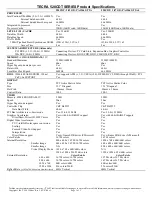
Page 194: ...A 4 User s Manual Specifications ...

Page 195: ...d external monitors A high resolution external monitor connected to the computer can display up to 2048 horizontal and 1536 vertical pixels at up to 16M colors The display controller also controls the video mode which uses industry standard rules to govern the screen resolution and the maximum number of colors that can be displayed on screen Software written for a given video mode will run on any ...

Page 196: ...bpp 60 75 85 100 1024x768 16bpp 60 75 85 100 32bpp 60 75 85 100 1280x8001 16bpp 60 32bpp 60 1280x1024 16bpp 60 75 85 100 32bpp 60 75 85 100 1600x1200 16bpp 60 75 85 100 32bpp 60 75 85 100 1920x1440 16bpp 60 75 32bpp 60 75 2048x1538 16bpp 60 32bpp 60 1 Some of display mode might not be supported depending on the external monitor which you use 2 If you are running some applications for example a 3D ...

Page 197: ...certified by the Wi Fi Alliance The Wi Fi CERTIFIED logo is a certification mark of the Wi Fi Alliance Network Operating System Microsoft Windows Networking Media Access Protocol CSMA CA Collision Avoidance with Acknowledgement ACK Data Rate 54 48 36 24 18 12 9 6 Mb s IEEE 802 11a g 11 5 5 2 1 Mb s IEEE 802 11 b The Wireless LAN feature is not available on all models ...

Page 198: ...e transmit rate of the wireless communication device Communications at a lower transmission rate may travel larger distances The range of your wireless devices can be affected when the antennas are placed near metal surfaces and solid high density materials Range is also impacted due to obstacles in the path of the transmission that may either absorb or reflect the radio signal Refer to the sheet ...

Page 199: ...stalling Wireless LAN cards the channel configuration is managed as follows For wireless clients that operate in a Wireless LAN Infrastructure the Wireless LAN card will automatically start operation at the channel identified by the Wireless LAN Access Point When roaming between different access points the station can dynamically switch to another channel if required In a Wireless LAN Access Point...

Page 200: ...C 4 User s Manual Wireless LAN ...

Page 201: ...ations Certification agencies Europe Length Minimum 1 7 meters Wire size Minimum 0 75 mm2 Current rating Minimum 2 5 amperes Voltage rating 125 or 250 VAC depending on country region s power standards U S and Canada UL listed and CSA certified No 18 AWG Type SVT or SPT 2 two conductor Australia AS Japan DENANHO Austria OVE Italy IMQ Belgium CEBEC The Netherlands KEMA Denmark DEMKO Norway NEMKO Fin...

Page 202: ... a 2 15P 250 V or 1 15P 125 V as designated in the U S National Electrical code handbook and the Canadian Electrical Code Part II The following illustrations show the plug shapes for the U S A and Canada the United Kingdom Australia and Europe USA and Canada UL approved CSA approved United Kingdom BS approved Australia AS approved Europe Approved by the appropriate agency ...

Page 203: ... not have all the features and specifications corresponding to all of the icons or switches shown on the computer chassis CPU Central Processing Unit CPU Performance Legal Footnotes CPU performance in your computer product may vary from specifications under the following conditions use of certain external peripheral products use of battery power instead of AC power use of certain multimedia comput...

Page 204: ...upport section in Chapter 9 Troubleshooting for more information 64 Bit Computing 64 bit processors are designed to take advantage of 32 and 64 bit computing 64 bit computing requires that the following hardware and software requirements are met 64 bit Operating System 64 bit CPU Chipset and BIOS Basic Input Output System 64 bit Device drivers 64 bit applications Certain device drivers and or appl...

Page 205: ...omputer operating system however reports storage capacity using powers of 2 for the definition of 1 GB 230 1 073 741 824 bytes and therefore shows less storage capacity Available storage capacity will also be less if the product includes one or more pre installed operating systems such as Microsoft Windows and or pre installed software applications or media content Actual formatted capacity may va...

Page 206: ...design and configuration and client design and software hardware configurations 54Mbps is the theoretical maximum speed under the IEEE802 11 a b g standard The actual transmission speed will be lower than the theoretical maximum speed Copy Protection Applicable copy protection standards included in certain media may prevent or limit recording or viewing of the media Images All images are simulated...

Page 207: ...Writable CMOS complementary metal oxide semiconductor CPU central processing unit CRT cathode ray tube DC direct current DDC display data channel DDR double data rate DIMM dual inline memory module DVD digital versatile disc DVD R Digital Versatile Disc Recordable DVD RAM Digital Versatile Disc Random Access Memory DVD R Dual Layer Digital Versatile Disc Recordable Dual Layer DVD ROM Digital Versa...

Page 208: ...t RAM random access memory RGB red green and blue ROM read only memory RTC real time clock S P DIF Sony Philips Digital Interface Format SDRAM synchronous dynamic random access memory SLI Scalable Link Interface SO DIMM small outline dual in line memory module SSD Solid state drive TFT thin film transistor USB Universal Serial Bus UXGA ultra extended graphics array VGA video graphics array WAN wid...

Page 209: ...that represent the most commonly used letters numbers and symbols B backup A copy of a file usually on a removable disk kept in case the original file is lost or damaged binary The base two number system composed of zeros and ones off or on used by most digital computers The right most digit of a binary number has a value of 1 the next a value of 2 then 4 8 16 and so on For example the binary numb...

Page 210: ... CD ROM CD ROM A Compact Disc Read Only Memory is a high capacity disc that can be read from but not written to The CD ROM drive uses a laser rather than magnetic heads to read data from the disc CD RW A Compact Disc ReWritable disc can be rewritten many times See also CD ROM character Any letter number punctuation mark or symbol used by the computer Also synonymous with byte chassis The frame con...

Page 211: ... computer that interprets and executes instructions CRT Cathode Ray Tube A vacuum tube in which beams projected on a fluorescent screen producing luminous spots An example is the television set cursor A small blinking rectangle or line that indicates the current position on the display screen D data Information that is factual measurable or statistical that a computer can process store or retrieve...

Page 212: ...ouse DVD An individual digital versatile or video disc See also DVD ROM DVD R R R A Digital Versatile Disc Recordable disk can be written once and read many times The DVD R drive uses a laser to read data from the disc DVD RAM A Digital Versatile Disc Random Access Memory is a high capacity high performance disc that lets you store large volumes of data The DVD ROM drive uses a laser to read data ...

Page 213: ...n electromechanical device that reads and writes to floppy diskettes folder An icon in Windows used to store documents or other folders format The process of readying a blank disk for its first use Formatting establishes the structure of the disk that the operating system expects before it writes files or programs onto the disk function keys The keys labeled F1 through F12 that tell the computer t...

Page 214: ...specify how to perform a particular task interface 1 Hardware and or software components of a system used specifically to connect one system or device to another 2 To physically connect one system or device to another to exchange information 3 The point of contact between user the computer and the program for example the keyboard or a menu interrupt request A signal that gives a component access t...

Page 215: ...temporarily such as RAM or it can be nonvolatile and hold data permanently such as ROM A computer s main memory is RAM See RAM ROM menu A software interface that displays a list of options on the screen Also called a screen microprocessor A hardware component contained in a single integrated circuit that carries out instructions Also called the central processing unit CPU one of the main parts of ...

Page 216: ...hrough the serial port of internal modem or 4 stored on some magnetic media P parallel Processes that occur simultaneously In communications it means the transmission of more than one bit of information at a time On your computer the parallel port provides a parallel communications interface between the computer and an appropriate device Compare serial parity 1 The symmetrical relationship between...

Page 217: ...ingent classification for home equipment use TOSHIBA portable computers comply with Class B computing device regulations Random Access Memory RAM Volatile memory that can be written to as well as read Volatile here means that information in RAM is lost when you turn off your computer This type of memory is used for your computer s main memory See also memory Compare ROM resolution A measure of the...

Page 218: ...computer system s activities See also hardware stop bit One or more bits of a byte that follow the transmitted character or group codes in asynchronous serial communications system disk A diskette that contains the operating system files needed to start the computer Any diskette can be formatted as a system disk A system disk is also called a bootable disk boot disk or a startup disk Compare non s...

Page 219: ...nnection using wireless communication components window A portion of the screen that can display its own application document or dialog box Often used to mean a Microsoft Windows window Wireless LAN Local Area Network LAN through wireless communication Wireless WAN Wide Area Network WAN through wireless communication write protection A method for protecting a floppy diskette from accidental erasur...

Page 220: ...Glossary 14 User s Manual Glossary ...

Page 221: ...er off 1 11 brightness decreases 5 4 brightness increases 5 4 controller 1 8 opening 3 4 Display controller B 1 E Equipment checklist 1 1 F Floppy disk using 4 13 Fn Esc sound mute 5 3 Fn F1 instant security 5 3 Fn F2 power save mode 5 3 Fn F3 Sleep Mode 5 3 Fn F4 hibernation 5 3 Fn F5 display selection 5 3 Fn F6 Display Brightness decreases 5 4 Fn F7 Display Brightness in creases 5 4 Fn F8 Wirele...

Page 222: ...tion 4 31 Monitor external 1 8 8 11 P PC card 8 2 inserting 8 2 removing 8 3 Ports 1 8 external monitor 1 8 USB 1 8 Power conditions 6 1 hibernation mode 3 8 indicator 6 3 panel power on off 1 12 6 14 shut Down mode Boot mode 3 6 Sleep Mode 3 6 system Auto Off 6 14 turning off 3 6 turning on 3 5 Power up modes 6 14 Problems AC power 9 5 analyzing 9 2 Battery 9 5 DVD Super Multi drive 9 9 Hard disk...

Page 223: ... Soft keys emulating keys on enhanced keyboard 5 2 ScrLock 5 3 Sound System 1 9 4 30 headphone jack 1 9 microphone jack 1 9 mute hot keys 5 3 T TOSHIBA ConfigFree 1 16 TOSHIBA Disc Creator 1 15 Touch Pad 1 8 location 2 7 using 4 1 U USB 1 8 V Video modes B 2 Video RAM 1 3 W Wireless communication switch 4 36 indicator 4 36 Wireless LAN 1 10 using 4 35 ...

Page 224: ...Index 4 User s Manual Index ...

Reviews: