4 Replacement Procedures
Satellite L450/Pro L450/L450D/Pro L450D Maintenance Manual
4-iii
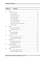
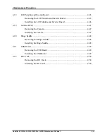
Disassembling the ODD Drive..................................................................... 4-18
Assembling the ODD Drive ......................................................................... 4-19
4.8
Keyboard Cover and Keyboard............................................................................ 4-20
Removing the Keyboard Cover and Keyboard ............................................ 4-20
Installing the keyboard Cover and Keyboard............................................... 4-22
4.9
Logic Upper Assembly......................................................................................... 4-23
Removing the Logic Upper Assembly ......................................................... 4-23
Installing the Logic Upper Assembly .......................................................... 4-24
4.10
Power Board......................................................................................................... 4-25
Removing the Power Board ......................................................................... 4-25
Installing the power switch board ................................................................ 4-25
4.11
Speakers ............................................................................................................... 4-26
Removing the Speakers................................................................................ 4-26
Installing the Speakers ................................................................................. 4-26
4.12
Touch Pad Bracket ............................................................................................... 4-27
Removing the Touch Pad Bracket................................................................ 4-27
Installing the Touch Pad Bracket ................................................................. 4-27
4.13
Thermal Fan ......................................................................................................... 4-28
Removing the Thermal Fan.......................................................................... 4-28
Installing the Thermal Fan ........................................................................... 4-28
4.14
Motherboard ......................................................................................................... 4-29
Removing the Motherboard ......................................................................... 4-29
Installing the Motherboard........................................................................... 4-31
4.15
CPU and Thermal Module ................................................................................... 4-33
Removing CPU and Thermal Module.......................................................... 4-33
Installing CPU and Thermal Module ........................................................... 4-35
4.16
Display Assembly ................................................................................................ 4-37
Removing the Display Assembly................................................................. 4-37
Installing the Display Assembly .................................................................. 4-38
4.17
LCD Bezel Assembly........................................................................................... 4-39
Removing the LCD Bezel Assembly ........................................................... 4-39
Installing the Display Mask ......................................................................... 4-40
Summary of Contents for Satellite L450 series
Page 1: ...Toshiba Personal Computer Satellite Maintenance Manual TOSHIBA CORPORATION CONFIDENTIAL ...
Page 14: ...Chapter 1 Hardware Overview ...
Page 17: ......
Page 33: ...Chapter 2 Troubleshooting Procedures 2 ...
Page 34: ......
Page 82: ...3 Tests and Diagnostics 1 Chapter 3 Tests and Diagnostics ...
Page 98: ...3 Tests and Diagnostics 17 Memory Write Test Memory Read Write Test ...
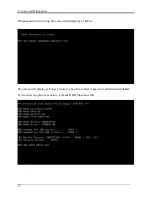
Page 104: ...3 Tests and Diagnostics 23 2 If the Magnetic switch test pass it will show below display ...
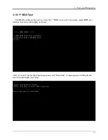
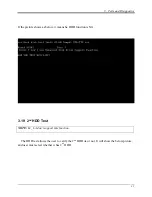
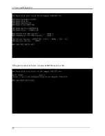
Page 119: ...3 Tests and Diagnostics 38 If the picture shows as below it means he HDD function is NG ...
Page 123: ...Chapter 4 Replacement Procedures ...
Page 209: ...3 Thai TI Keyboard Figure TI keyboard 4 Korean KO Keyboard Figure KO keyboard ...
Page 211: ...7 Hebrew HB Keyboard Figure HB keyboard 8 Danish DM Keyboard Figure DM keyboard ...
Page 212: ...9 Swiss SW Keyboard Figure SW keyboard 10 Arabic ARE Keyboard Figure ARE keyboard ...
Page 213: ...11 Czech CZ Keyboard Figure CZ keyboard 12 Russian RU Keyboard Figure RU keyboard ...
Page 214: ...13 Portuguese PO Keyboard Figure PO keyboard 14 Slovakian SL Keyboard Figure SL keyboard ...
Page 215: ...15 Italian IT Keyboard Figure IT keyboard 16 French FR Keyboard Figure FR keyboard ...
Page 216: ...17 German GR Keyboard Figure GR keyboard 18 Greek GK Keyboard Figure GK keyboard ...
Page 217: ...19 Canada French CF Keyboard Figure CF keyboard 20 Hungarian HG Keyboard Figure HG keyboard ...
Page 218: ...21 Spanish SP Keyboard Figure SP keyboard 22 Turkish TR Keyboard Figure TR keyboard ...
Page 219: ...3 Turkish F TF F Keyboard Figure TF F keyboard 24 Swedish SD Keyboard Figure SD keyboard ...
Page 220: ...25 Belgian BE Keyboard Figure BE keyboard 26 Yugoslavian YU Keyboard Figure YU keyboard ...
Page 221: ...27 Norwegian NW Keyboard Figure NW keyboard 28 Scandinavian ND Keyboard Figure ND keyboard ...
Page 223: ...31 Japanese JP Keyboard Figure JP keyboard 32 Romania RO Keyboard Figure RO keyboard ...

