4 Replacement Procedures
Satellite L450/Pro L450/L450D/Pro L450D Maintenance Manual
4-v
Figures
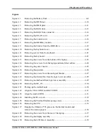
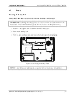
Figure 4.1
Removing the Battery Pack ........................................................................... 4-8
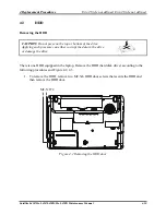
Figure 4.2
Removing the HDD door ............................................................................. 4-10
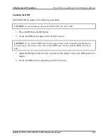
Figure 4.3
Removing the HDD plate............................................................................. 4-11
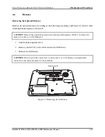
Figure 4.4
Removing the RAM door............................................................................. 4-13
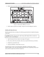
Figure 4.5
Removing the RAM from connector ........................................................... 4-14
Figure 4.6
Removing the WLAN card .......................................................................... 4-15
Figure 4.7
Removing the modem card .......................................................................... 4-16
Figure 4.8
Removing the ODD Bay module................................................................. 4-17
Figure 4.9
Removing the bracket from the ODD drive................................................. 4-18
Figure 4.10 Removing the keyboard cover ..................................................................... 4-20
Figure 4.11 Removing screws from the keyboard .......................................................... 4-21
Figure 4.12 Removing the keyboard ............................................................................... 4-21
Figure 4.13 Removing the screws from the bottom of the laptop................................... 4-23
Figure 4.14 Removing five screws from the laptop and detach four cables. .................. 4-24
Figure 4.15 Removing the power board.......................................................................... 4-25
Figure 4.16 Removing the speakers ................................................................................ 4-26
Figure 4.17 Removing the screws from the touch pad bracket ....................................... 4-27
Figure 4.18 Removing the thermal fan from the logic lower assembly .......................... 4-28
Figure 4.19 Removing motherboard from logic lower assembly.................................... 4-29
Figure 4.20 Removing the DC_IN .................................................................................. 4-30
Figure 4.21 Picking up the motherboard......................................................................... 4-30
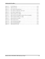
Figure 4.22 Align the VGA CONN and RJ45 CONN .................................................... 4-31
Figure 4.23 Align the Audio CONN ............................................................................... 4-31
Figure 4.24 Installing the DC-in jack.............................................................................. 4-32
Figure 4.25 Removing the Thermal Module spring screws ............................................ 4-34
Figure 4.26 Removing the CPU ...................................................................................... 4-35
Figure 4.27 Reapply the Shinetsu 7726 grease on the thermal module and
remove the release papers ............................................................................ 4-36
Figure 4.28 Removing the screws from the rear of the laptop........................................ 4-37
Figure 4.29 Removing the display assembly................................................................... 4-37
Figure 4.30 Removing the LCD Bezel Assembly........................................................... 4-39
Summary of Contents for Satellite L450 series
Page 1: ...Toshiba Personal Computer Satellite Maintenance Manual TOSHIBA CORPORATION CONFIDENTIAL ...
Page 14: ...Chapter 1 Hardware Overview ...
Page 17: ......
Page 33: ...Chapter 2 Troubleshooting Procedures 2 ...
Page 34: ......
Page 82: ...3 Tests and Diagnostics 1 Chapter 3 Tests and Diagnostics ...
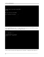
Page 98: ...3 Tests and Diagnostics 17 Memory Write Test Memory Read Write Test ...
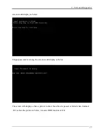
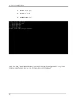
Page 104: ...3 Tests and Diagnostics 23 2 If the Magnetic switch test pass it will show below display ...
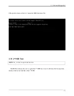
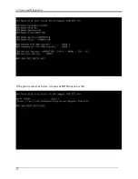
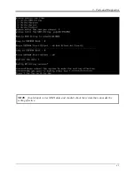
Page 119: ...3 Tests and Diagnostics 38 If the picture shows as below it means he HDD function is NG ...
Page 123: ...Chapter 4 Replacement Procedures ...
Page 209: ...3 Thai TI Keyboard Figure TI keyboard 4 Korean KO Keyboard Figure KO keyboard ...
Page 211: ...7 Hebrew HB Keyboard Figure HB keyboard 8 Danish DM Keyboard Figure DM keyboard ...
Page 212: ...9 Swiss SW Keyboard Figure SW keyboard 10 Arabic ARE Keyboard Figure ARE keyboard ...
Page 213: ...11 Czech CZ Keyboard Figure CZ keyboard 12 Russian RU Keyboard Figure RU keyboard ...
Page 214: ...13 Portuguese PO Keyboard Figure PO keyboard 14 Slovakian SL Keyboard Figure SL keyboard ...
Page 215: ...15 Italian IT Keyboard Figure IT keyboard 16 French FR Keyboard Figure FR keyboard ...
Page 216: ...17 German GR Keyboard Figure GR keyboard 18 Greek GK Keyboard Figure GK keyboard ...
Page 217: ...19 Canada French CF Keyboard Figure CF keyboard 20 Hungarian HG Keyboard Figure HG keyboard ...
Page 218: ...21 Spanish SP Keyboard Figure SP keyboard 22 Turkish TR Keyboard Figure TR keyboard ...
Page 219: ...3 Turkish F TF F Keyboard Figure TF F keyboard 24 Swedish SD Keyboard Figure SD keyboard ...
Page 220: ...25 Belgian BE Keyboard Figure BE keyboard 26 Yugoslavian YU Keyboard Figure YU keyboard ...
Page 221: ...27 Norwegian NW Keyboard Figure NW keyboard 28 Scandinavian ND Keyboard Figure ND keyboard ...
Page 223: ...31 Japanese JP Keyboard Figure JP keyboard 32 Romania RO Keyboard Figure RO keyboard ...

