Error! Style not defined.
Error! Style not defined.
4 Replacement Procedures
4.1
General
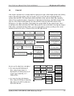
This chapter explains how to disassemble the laptop and replace Field Replaceable Units (FRUs).
Some replacement procedures may not require you to remove all the surrounding FRUs to
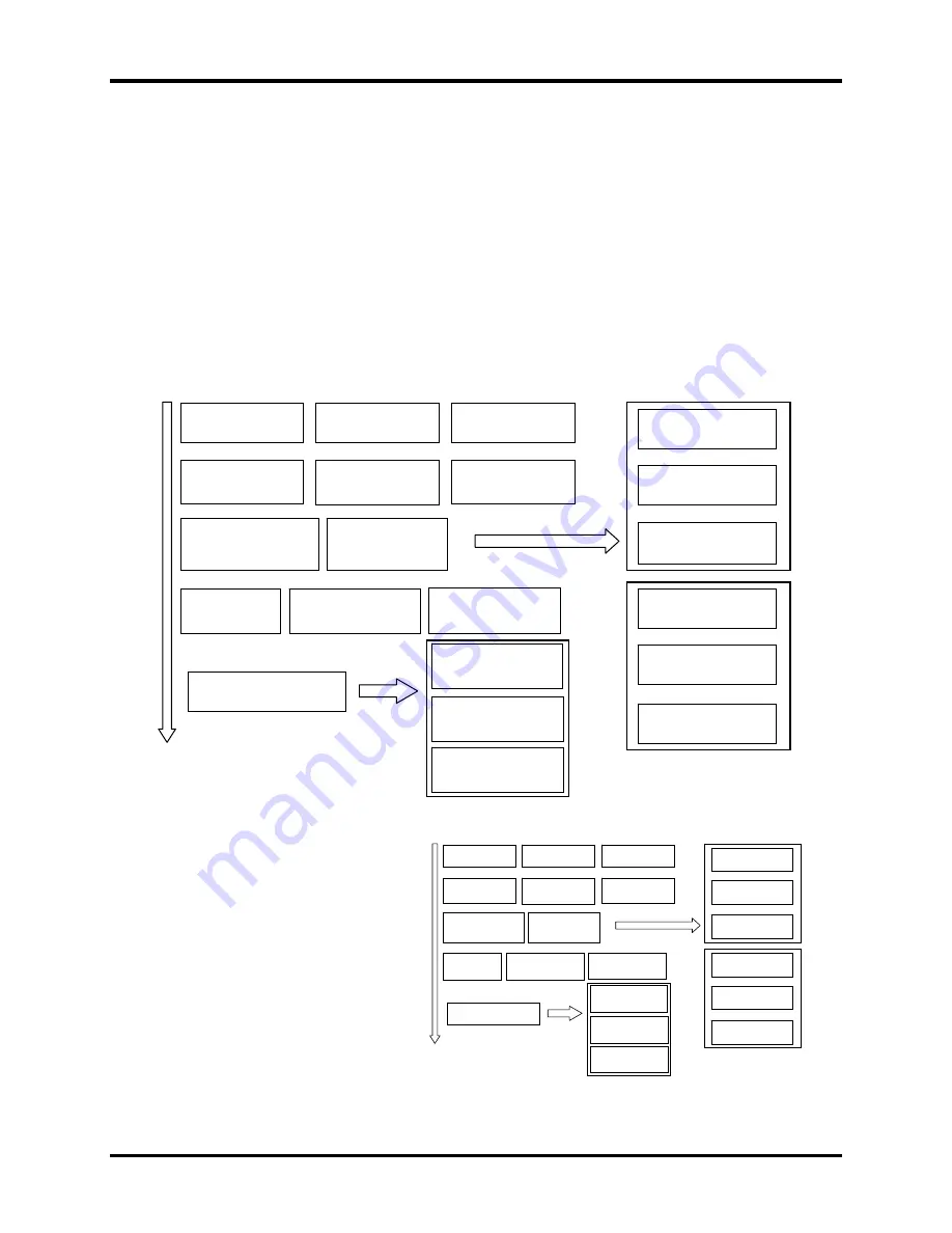
replace only one FRU. The chart below shows the FRUs in the order in which they should be
removed in a top-down manner, irrespective of their physical locations. The FRUs shown in the
top area of the chart should normally be removed before removing the FRUs shown in the
bottom area. To replace the FRUs, first identify the suspect FRU for the system failure. Next,
according to this chart, determine the FRUs that need to be removed before removing the suspect
FRU. After you determine those FRUs, go to the appropriate sections according to the section
numbers shown in the boxes. Then start removal and replacement.
4.2 Battery
4.3 HDD
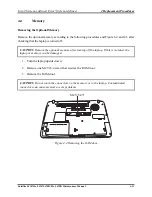
4.4 Memory
4.8 Keyboard Cover
and Keyboard
4.14 Motherboard
4.11 Speakers
4.12 Touch Pad
Bracket
4.10 Power Board
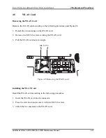
4.5 WLAN Card
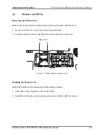
4.6 Modem Card
(BTO)
4.7 ODD
4.9 Logic Upper
Assembly
4.13 Thermal
Fan
4.15 CPU and
Thermal Module
4.21 USB Board
4.20 Hinge Saddle
4.22 RJ11 Jack
4.16 Display Assembly
4.17 LCD Bezel
Assembly
4.18 LCD Module
and Inverter Board
4.19 Camera
How to use the chart (two examples):
For removing the Motheroard:
First, remove parts from 4.8
Keyboard Cover & Keyboard, 4.9
Logic Upper Assembly, 4.13
Thermal Fan.
For removing the LCD Module:
First, remove LCD Bezel Assembly,
then remove the LCD module and
the Inverter Board.
4.2 Battery
4.3 HDD
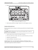
4.4 Memory
4.8 Keyboard Cover
and Keyboard
4.14 Motherboard
4.11 Speakers
4.12 Touch Pad
Bracket
4.10 Power Board
4.5 WLAN Card
4.6 Modem Card
(BTO)
4.7 ODD
4.9 Logic Upper
Assembly
4.13 Thermal
Fan
4.15 CPU and
Thermal Module
4.21 USB Board
4.20 Hinge Saddle
4.22 RJ11 Jack
4.16 Display Assembly
4.17 LCD Bezel
Assembly
4.18 LCD Module
and Inverter Board
4.19 Camera
Satellite L450/Pro L450/L450D/Pro L450D Maintenance Manual
4-1
Summary of Contents for Satellite L450 series
Page 1: ...Toshiba Personal Computer Satellite Maintenance Manual TOSHIBA CORPORATION CONFIDENTIAL ...
Page 14: ...Chapter 1 Hardware Overview ...
Page 17: ......
Page 33: ...Chapter 2 Troubleshooting Procedures 2 ...
Page 34: ......
Page 82: ...3 Tests and Diagnostics 1 Chapter 3 Tests and Diagnostics ...
Page 98: ...3 Tests and Diagnostics 17 Memory Write Test Memory Read Write Test ...
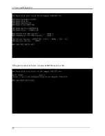
Page 104: ...3 Tests and Diagnostics 23 2 If the Magnetic switch test pass it will show below display ...
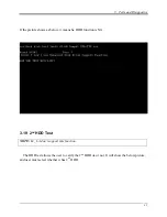
Page 119: ...3 Tests and Diagnostics 38 If the picture shows as below it means he HDD function is NG ...
Page 123: ...Chapter 4 Replacement Procedures ...
Page 209: ...3 Thai TI Keyboard Figure TI keyboard 4 Korean KO Keyboard Figure KO keyboard ...
Page 211: ...7 Hebrew HB Keyboard Figure HB keyboard 8 Danish DM Keyboard Figure DM keyboard ...
Page 212: ...9 Swiss SW Keyboard Figure SW keyboard 10 Arabic ARE Keyboard Figure ARE keyboard ...
Page 213: ...11 Czech CZ Keyboard Figure CZ keyboard 12 Russian RU Keyboard Figure RU keyboard ...
Page 214: ...13 Portuguese PO Keyboard Figure PO keyboard 14 Slovakian SL Keyboard Figure SL keyboard ...
Page 215: ...15 Italian IT Keyboard Figure IT keyboard 16 French FR Keyboard Figure FR keyboard ...
Page 216: ...17 German GR Keyboard Figure GR keyboard 18 Greek GK Keyboard Figure GK keyboard ...
Page 217: ...19 Canada French CF Keyboard Figure CF keyboard 20 Hungarian HG Keyboard Figure HG keyboard ...
Page 218: ...21 Spanish SP Keyboard Figure SP keyboard 22 Turkish TR Keyboard Figure TR keyboard ...
Page 219: ...3 Turkish F TF F Keyboard Figure TF F keyboard 24 Swedish SD Keyboard Figure SD keyboard ...
Page 220: ...25 Belgian BE Keyboard Figure BE keyboard 26 Yugoslavian YU Keyboard Figure YU keyboard ...
Page 221: ...27 Norwegian NW Keyboard Figure NW keyboard 28 Scandinavian ND Keyboard Figure ND keyboard ...
Page 223: ...31 Japanese JP Keyboard Figure JP keyboard 32 Romania RO Keyboard Figure RO keyboard ...

