2 Troubleshooting Procedures
Satellite L450D/455D, Satellite pro L450D Series Maintenance Manual
29
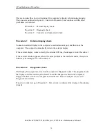
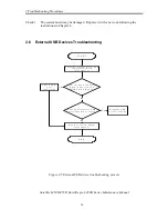
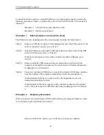
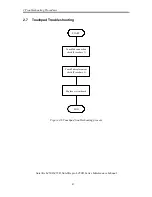
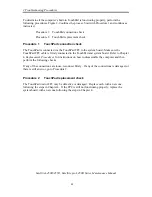
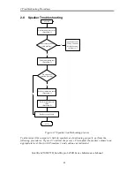
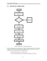
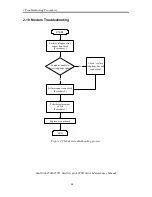
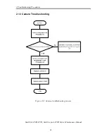
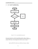
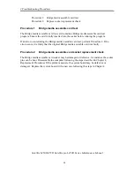
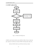
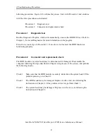
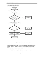
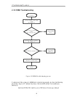
This section describes how to determine if the computer's modem is functioning properly.
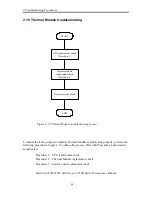
Figure 2-9 outlines the process. Perform the steps below starting with Procedure 1 and
continuing with the other procedures as required.
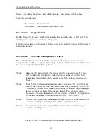
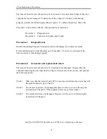
Procedure 1: Telephone line connection check
Procedure 2: Modem card connection check
Procedure 3: Modem card replacement check
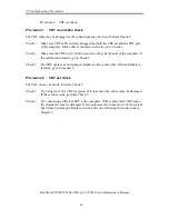
Procedure 1
Telephone line connection check
The telephone cable may be damaged or the connections may be loose. Attempt to connect
the computer to a network through using the modem. If the modem does not function at all,
go to Procedure 3. If the attempt fails because the computer detects no telephone signal, the
fault may be in the telephone cable, the wall socket or the modem port. Perform Check 1:
Check 1
Make sure telephone cable is firmly plugged into both the telephone wall socket
and the modem port of the computer. If the cable is connected correctly, go to
Check 2.
Check 2
Make sure the modem port is firmly secured to the system board of the computer.
If the malfunction remains, go to Check 3.
Check 3
The telephone cable may be damaged. Replace with a good cable. If the
malfunction remains, go to Procedure 2.
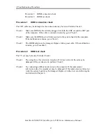
Procedure 2
Modem card connection check
Disassemble the computer following the steps described in Chapter 4,
Replacement
Procedures
and ensure that the modem card is well connected to the system board. If the
problem persists, perform Procedure 3.
Procedure 3
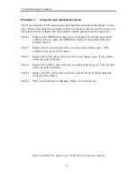
Modem replacement check
The modem card or RJ-11 jack may be faulty. Try replacing them. If the problem persists, the
system board may be defective or damaged. Replace the System Board with a new one
following the steps in Chapter 4,
Replacement Procedures
.
Summary of Contents for Satellite L450 series
Page 1: ...Toshiba Personal Computer Satellite Maintenance Manual TOSHIBA CORPORATION CONFIDENTIAL ...
Page 14: ...Chapter 1 Hardware Overview ...
Page 17: ......
Page 33: ...Chapter 2 Troubleshooting Procedures 2 ...
Page 34: ......
Page 82: ...3 Tests and Diagnostics 1 Chapter 3 Tests and Diagnostics ...
Page 98: ...3 Tests and Diagnostics 17 Memory Write Test Memory Read Write Test ...
Page 104: ...3 Tests and Diagnostics 23 2 If the Magnetic switch test pass it will show below display ...
Page 119: ...3 Tests and Diagnostics 38 If the picture shows as below it means he HDD function is NG ...
Page 123: ...Chapter 4 Replacement Procedures ...
Page 209: ...3 Thai TI Keyboard Figure TI keyboard 4 Korean KO Keyboard Figure KO keyboard ...
Page 211: ...7 Hebrew HB Keyboard Figure HB keyboard 8 Danish DM Keyboard Figure DM keyboard ...
Page 212: ...9 Swiss SW Keyboard Figure SW keyboard 10 Arabic ARE Keyboard Figure ARE keyboard ...
Page 213: ...11 Czech CZ Keyboard Figure CZ keyboard 12 Russian RU Keyboard Figure RU keyboard ...
Page 214: ...13 Portuguese PO Keyboard Figure PO keyboard 14 Slovakian SL Keyboard Figure SL keyboard ...
Page 215: ...15 Italian IT Keyboard Figure IT keyboard 16 French FR Keyboard Figure FR keyboard ...
Page 216: ...17 German GR Keyboard Figure GR keyboard 18 Greek GK Keyboard Figure GK keyboard ...
Page 217: ...19 Canada French CF Keyboard Figure CF keyboard 20 Hungarian HG Keyboard Figure HG keyboard ...
Page 218: ...21 Spanish SP Keyboard Figure SP keyboard 22 Turkish TR Keyboard Figure TR keyboard ...
Page 219: ...3 Turkish F TF F Keyboard Figure TF F keyboard 24 Swedish SD Keyboard Figure SD keyboard ...
Page 220: ...25 Belgian BE Keyboard Figure BE keyboard 26 Yugoslavian YU Keyboard Figure YU keyboard ...
Page 221: ...27 Norwegian NW Keyboard Figure NW keyboard 28 Scandinavian ND Keyboard Figure ND keyboard ...
Page 223: ...31 Japanese JP Keyboard Figure JP keyboard 32 Romania RO Keyboard Figure RO keyboard ...

