Replacement Procedures
4.9 Top assembly
Removing the Top assembly
The following describes the procedure of removing the cover assembly.
1.
Turn over the computer.
2.
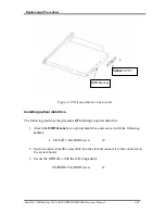
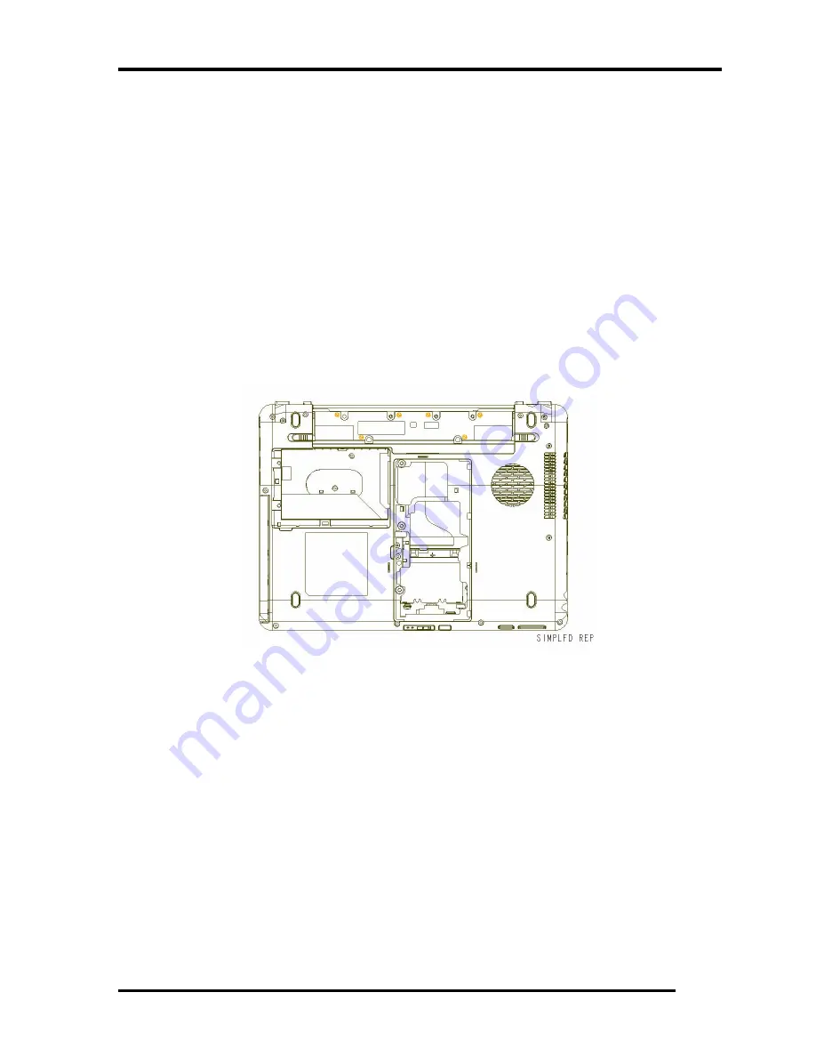
Remove the following
screws
securing the cover assembly from the back and bottom
of computer.
•
M2.0
×
5.0 FLAT BIND screw Back x9
•
M2.5
×
8 FLAT BIND screw Back x4
Figure 4-14 remove the screws (back)
3.
Disconnect the
touch pad flat cable/Fingerprint cable/Bluetooth Cable
from the
connector on the system board.
Satellite U400/Satellite Pro U400/PORTEGE M800
Maintenance Manual 28
Summary of Contents for Satellite Pro U400 Series
Page 110: ...Test Program for Field Satellite U400 and Satellite Pro U400 Tests and Diagnostics Manual 17 ...
Page 168: ...Replacement Procedures Satellite U400 Satellite Pro U400 PORTEGE M800 Maintenance Manual 4 iv ...
Page 276: ...Pin Assignment 36 Satellite U400 Satellite Pro U400 PORTEGE M800 Maintenance Manual ...
Page 302: ...Wiring Diagrams F 2 Satellite U400 Satellite Pro U400 PORTEGE M800 Maintenance Manual ...


