background image

User’s Manual

9-4

Troubleshooting

Power

When the computer is not plugged into an AC outlet, the battery pack is the 

primary power source. However, your computer has a number of other 

power resources, including an intelligent power supply and a Real Time 

Clock battery. These resources are interrelated and any one could affect 

apparent power problems. This section provides checklists for AC power 

and the battery. If you cannot resolve a problem after following them, the 

cause could lie with another power resource. In such a case, contact your 

dealer. 

Overheating power down 

If the computer's internal temperature becomes too high, the computer will 

automatically enter Hibernation Mode or Sleep Mode and shut down. If the 

computer has reached room temperature and still does not start, or if it 

starts but shuts down quickly contact your dealer. 

AC power

If you have trouble turning on the computer with the AC adaptor connected, 

check the 

Battery

 indicator. Refer to Chapter 6, 

Power and Power-Up 

Modes

 for more information. 

Problem 

Procedure

AC adaptor doesn’t 

power the computer 

Check the connections. Make sure the cord is 

firmly connected to the computer and a power 

outlet. 
Check the condition of the cord and terminals. If 

the cord is frayed or damaged, replace it. If the 

terminals are soiled, wipe them with cotton or a 

clean cloth. 
If the AC adaptor still does not power the 

computer, contact your dealer. 

Summary of Contents for Satellite U305-S2812

Page 1: ...computers toshiba europe com User s Manual U300 ...

Page 2: ... the copyrighted works or perform other actions Please note that you may infringe the owner s rights protected by the copyright laws if you use the screen mode switching functions e g Wide mode Wide Zoom mode etc of this product to display enlarged images video at coffee shops or hotels for the purposes of profits or providing these to the public Disclaimer This manual has been validated and revie...

Page 3: ...trademark of Ulead Systems Inc Other trademarks and registered trademarks not listed above may be used in this manual EU Declaration of Conformity TOSHIBA declares that this product conforms to the following Standards This product is carrying the CE Mark in accordance with the related European Directives Responsible for CE Marking is TOSHIBA Europe Hammfelddamm 8 41460 Neuss Germany GOST Supplemen...

Page 4: ... with the following networks It has been tested to and found to conform with the additional requirements conditional in EG 201 121 Specific switch settings or software setup are required for each network please refer to the relevant sections of the user guide for more details The hookflash timed break register recall function is subject to separate national type approvals It has not been tested fo...

Page 5: ...ly disposed as inappropriate waste handling of this product may cause potential hazards to the environment and human health For more detailed information about recycling of this product please contact your local city office your household waste disposal service or the shop where you purchased the product This symbol may not stick depending on the country and region where you purchased ...

Page 6: ...ser system To ensure proper use of this product please read this instruction manual carefully and retain for future reference Should the unit ever require maintenance contact an authorized service location Use of controls adjustments or the performance of procedures other than those specified may result in hazardous radiation exposure To prevent direct exposure to the laser beam do not try to open...

Page 7: ...his instruction manual carefully and retain for future reference Should the unit ever require maintenance contact an authorized service location Use of controls adjustments or the performance of procedures other than those specified may result in hazardous radiation exposure To prevent direct exposure to the laser beam do not try to open the enclosure ...

Page 8: ...nual carefully and keep this manual for your future reference In case of any trouble with this model please contact your nearest AUTHORIZED service station To prevent direct exposure to the laser beam do not try to open the enclosure CAUTION USE OF CONTROLS OR ADJUSTMENTS OR PERFORMANCE OF PROCEDURES OTHER THAN THOSE SPECIFIED IN THE OWNER S MANUAL MAY RESULT IN HAZARDOUS RADIATION EXPOSURE ...

Page 9: ...te ventilation Otherwise they may overheat To keep your computer in prime operating condition protect your work area from Dust moisture and direct sunlight Equipment that generates a strong electromagnetic field such as stereo speakers other than speakers that are connected to the computer or speakerphones Rapid changes in temperature or humidity and sources of temperature change such as air condi...

Page 10: ...t as the material could become damaged Pressure or impact damage Do not apply heavy pressure to the computer or subject it to any form of strong impact as this can damage the computer s components or otherwise cause it to malfunction PC and Express Card overheating Some PC and Express Cards can become hot during prolonged use which may result in errors or instability in the operation of the device...

Page 11: ...r 2 The Grand Tour Front with the display closed 2 1 Left side 2 2 Right side 2 3 Backside 2 5 Underside 2 5 Front with the display open 2 6 Fixed optical media drives 2 8 AC adaptor 2 10 Chapter 3 Getting Started Installing the battery pack 3 1 Connecting the AC adaptor 3 2 Opening the display 3 4 Turning on the power 3 5 Turning off the power 3 5 Restarting the computer 3 8 System Recovery Optio...

Page 12: ...omputer 4 24 Using the Hard Disk Drive HDD Protection depends on the model purchased 4 24 Chapter 5 The Keyboard Typewriter keys 5 1 F1 F12 function keys 5 2 Soft keys Fn key combinations 5 2 Hot keys 5 3 Windows special keys 5 5 Keypad overlay 5 5 Generating ASCII characters 5 6 Chapter 6 Power and Power Up Modes Power conditions 6 1 Power indicators 6 2 Battery types 6 3 Care and use of the batt...

Page 13: ... adaptor 8 10 External monitor 8 10 Security lock 8 10 Chapter 9 Troubleshooting Problem solving process 9 1 Hardware and system checklist 9 3 TOSHIBA support 9 14 Appendix A Specifications Appendix B Display Controller and Modes Appendix C Wireless LAN Appendix D AC Power Cord and Connectors Appendix E Legal Footnotes Appendix F If your computer is stolen Glossary Index ...

Page 14: ...ading the preface to learn how this manual is organized then become acquainted with this manual by browsing through its pages Be sure to look over the Specifications section of the Introduction to learn about features that are uncommon or unique to the computer If you are going to install PC Cards or connect external devices such as a monitor be sure to read Chapter 8 Optional Devices Manual conte...

Page 15: ...Glossary defines general computer terminology and includes a list of acronyms used in the text The Index quickly directs you to the information contained in this manual Conventions This manual uses the following formats to describe identify and highlight terms and operating procedures Abbreviations On first appearance and whenever necessary for clarity abbreviations are enclosed in parentheses fol...

Page 16: ...elow ABC When procedures require an action such as clicking an icon or entering text the icon s name or the text you are to type in is represented in the type face you see to the left ABC Names of windows or icons or text generated by the computer that appears on its display screen is presented in the type face you see to the left Pay attention A caution informs you that improper use of equipment ...

Page 17: ...attery pack Installed or separate from the computer Software The following software is preinstalled Microsoft Windows Vista Microsoft Internet Explorer TOSHIBA Value Added Package TOSHIBA Hardware Setup TOSHIBA Supervisor Password TOSHIBA Assist TOSHIBA ConfigFree TOSHIBA DVD Player TOSHIBA CD DVD Acoustic Silencer TOSHIBA SD Utilities Some of the features described in this manual may not function...

Page 18: ...a and additional Software Product Recovery DVD ROM Features Please visit your region s web site for the configuration details of the model that you have purchased Processor If any of the items are missing or damaged contact your dealer immediately Built in Depend on the model you purchased Intel Core 2 Duo Processor Intel Core Duo Processor Intel Pentium Dual Core Processor Intel Celeron M Process...

Page 19: ...aximum of 4 GB system memory total Video RAM The amount of Video RAM available is dependent on the computer s system memory Start Control Panel Appearance and Personalization Personalization Display Settings The amount of Video RAM can be verified by clicking the Advanced Settings button in the Display Settings window Battery Pack Your computer is powered by a rechargeable lithium ion battery pack...

Page 20: ...if the product includes one or more pre installed operating systems such as Microsoft Operating System and or pre installed software applications or media content Actual formatted capacity may vary Hard disk Drive Available in four sizes 80 0 billion bytes 74 51 GB 120 0 billion bytes 111 75 GB 160 0 billion bytes 149 01 GB 200 0 billion bytes 186 26 GB Other hard disk drives may be introduced in ...

Page 21: ... 8 speed DVD RW s at maximum 6 speed DVD R s at maximum 8 speed DVD RW s at maximum 8 speed DVD R DL discs at maximum 4 speed and DVD R DL discs at maximun 4 speed DVD RAM at maximum 5 speed This drive supports the following formats in addition to DVD ROM CD R RW drive DVD R DVD RW DVD RAM DVD R DVD RW DVD R DL DVD R DL Built In 13 3 WXGA 16 million colors with the following resolution 1280 horizo...

Page 22: ...external devices such as digital video cameras Express Card The Express Card expansion slot that can accommodate two standard module formats an Express Card 34 module and an Express Card 54 module An Express Card module is a small add in card technology based on the PCI Express and Universal Serial Bus USB interfaces Multiple Digital Media Card Slot Supports SD Mini SD with adaptor MMS MS MS Pro x...

Page 23: ... per second 10BASE T and Fast Ethernet LAN 100 megabits per second 100BASE TX Wireless LAN The Wireless LAN feature is not available on all models Where present it supports the A B G and N standards but it is compatible with other LAN systems based on Direct Sequence Spread Spectrum Orthogonal Frequency Division Multiplexing radio technology that complies with the IEEE 802 11 Standard Password Pow...

Page 24: ...s voltage overload from an AC adaptor This can be specified in the Power Options Battery Save Mode 1 This feature lets you save battery power This can be specified in the Power Options Panel Power On Off 1 This feature turns power to the computer off when the display panel is closed and turns it back on when the panel is opened This can be specified in the Power Options Low Battery Automatic Hiber...

Page 25: ...BA Power Saver TOSHIBA Power Saver provides you with the features of more various power supply managements TOSHIBA Zooming Utility This utility allows you to enlarge or reduce the icon size on the Windows Desktop or the zoom factor associated with specific supported applications TOSHIBA PC Diagnostic Tool The TOSHIBA PC Diagnostic Tool will display basic system configuration information and allow ...

Page 26: ... a user password select the SECURE tab on TOSHIBA Assist then start the User password utility On the Password tab you can register a user password TOSHIBA DVD Player The DVD Player is used to play DVD Video It has an on screen interface and functions Click point to All Programs point to TOSHIBA DVD Player then click TOSHIBA DVD Player TOSHIBA Disc Creator You can create CD DVDs in several formats ...

Page 27: ...s the operating system default Two additional tiles are also added to your Mobility Center Installing the TOSHIBA Extended Tiles for Windows Mobility Center package will add the following functions Lock Computer Lock your computer without turning it off This has the same function as the Lock button at the bottom of the right pane of the start menu TOSHIBA Assist Open the TOSHIBA Assist if it is al...

Page 28: ...Slot DC in LED Power LED Hard Disk Drive LED Battery LED Multiple Digital Media Card Slot LED i LINK IEEE1394a Port This port allows you to connect an external device such as a digital video camera for highspeed data transfer Depends on the model you purchased Multiple Digital Media Card Slot Supports SD mini SD with adaptor MMS MS MS PRO xD SDHC media cards Wireless Communication Switch The Wirel...

Page 29: ...Sleep Mode Battery LED The Battery indicator shows the condition of the battery s charge Blue indicates a full charge orange indicates that the battery is charging and flashing orange indicates a low battery charge Refer to Chapter 6 Power and Power Up Modes Hard Disk Drive LED The Hard Disk Drive LED indicates that the hard disk drive is being accessed Every time your computer runs a program open...

Page 30: ...al Bus ports are on the left side The ports comply with the USB 2 0 standard which enable data transfer speeds 40 times faster than the USB 1 1 standard The ports also support USB 1 1 Keep foreign objects out of the USB connectors A pin or similar object can damage the computer s circuitry Operation of all functions of all USB devices has not been confirmed As such some untested third party device...

Page 31: ...eds 40 times faster than the USB 1 1 standard The ports also support USB 1 1 Keep foreign objects out of the USB connectors A pin or similar object can damage the computer s circuitry Operation of all functions for all USB devices has not been confirmed As such some untested third party devices may not function properly LAN Jack This jack lets you connect to a LAN The adaptor has built in support ...

Page 32: ...sure the display is closed before turning over your computer The underside of the computer DC in 19V Jack DC IN 19V Jack The AC adaptor connects to this socket Use only the model of AC adaptor that comes with the computer Using the wrong adaptor can damage your computer Battery Pack Battery Release Latch 2 Cooling Vents Battery Release Lock 1 Hard Disk Cover Memory Module and Wireless LAN Cover ...

Page 33: ...se Lock 1 Slide this lock to prepare the battery pack for removal Battery Pack The battery pack powers the computer when the AC adaptor is not connected For detailed information on the battery pack refer to Chapter 6 Power and Power Up Modes Battery Release Latch 2 Slide and hold this latch to release the battery pack for removal For detailed information on removing the battery pack refer to Chapt...

Page 34: ...rnet Button or Press this button to launch an Internet browser If the computer s power is off you can press this button to turn on the computer s power and launch the browser automatically in one step Assist Button Press this button to launch the TOSHIBA Assist Depends on the model you purchased CD DVD Button or Pressing this button will launch an application program that allows for playing of CDs...

Page 35: ... can write Use TOSHIBA Disc Creator to write compact discs Refer to Chapter 4 Operating Basics Previous Button Skips backwards to the previous track chapter or digital file Refer to Chapter 4 Operating Basics for details Depends on the model purchased Next Button Skips forward to the next track chapter or digital file Refer to Chapter 4 Operating Basics for details Depends on the model purchased T...

Page 36: ...dio CD only DVD Video CD Text CD ROM Mode 1 Mode 2 Enhanced CD CD EXTRA CD RW DVD Super Multi drive Supporting DVD R Double Layer The full size DVD Super Multi drive module lets you record data to writable CD DVDs as well as run either 12 cm 4 72 or 8 cm 3 15 CD DVDs without using an adaptor The read speed is slower at the centre of a disc and faster at the outer edge DVD read 8 speed maximum DVD ...

Page 37: ...or an equivalent optional adaptor Use of the wrong adaptor could damage your computer TOSHIBA assumes no liability for any damage in such case Use only the AC Adaptor supplied with your computer or an equivalent adaptor that is compatible Use of any incompatible adaptor or other types of AC Adaptors may have a different voltage which could cause damage to your computer computer failure and or poss...

Page 38: ...attery Release Lock 1 to ensure the battery is locked into place Later when you want to remove the battery you must disengage this lock first Be sure also to read the Safety Instruction Manual This guide which is included with the computer explains product liability All users should be sure to read the section Windows Vista setup The battery pack is a lithium ion battery which can explode if not p...

Page 39: ... connected to any power source supplying from 100 to 240 volts and 50 or 60 hertz For details on using the AC adaptor to charge the battery pack refer to Chapter 6 Power and Power Up Modes Battery Release Lock 1 Battery Release Latch 2 Refer to Removing the battery pack section in Chapter 6 Power and Power Up Modes for removing the battery pack Use only the AC adaptor supplied as an accessory Othe...

Page 40: ...daptor that is compatible Use of any incompatible adaptor could damage your computer TOSHIBA assumes no liability for any damage caused by use of an incompatible adaptor When you connect the AC adaptor to the computer always follow the steps in the exact order as described in the User s Manual Connecting the power cable to a live electrical outlet should be the last step otherwise the adaptor DC o...

Page 41: ... be rotated in a wide range of angles for optimal viewing 1 Lift the panel up and adjust it to the best viewing angle for you Opening the display Use reasonable care when opening and closing the display panel Opening it vigorously or slamming it shut could damage the computer ...

Page 42: ...screen 1 If you have entered data save it to the hard disk 2 Make sure all disk disc activity has stopped then remove the CD DVDs 3 Click then click the arrow icon located in the power management button From the pull down menu choose Shut Down 4 Turn off the power to any peripheral devices After you turn on the power for the first time do not turn it off until you have set up the operating system ...

Page 43: ...and Maintenance Power Options Click click power button located in the power management buttons or click arrow button and select Sleep from the menu When the AC adaptor is connected the computer will go into Sleep Mode according to the settings in the Power Options To restore operation from Sleep Mode press the power button or press any key The latter action works only if Wake up on Keyboard is ena...

Page 44: ...the computer automatically shuts down because of a low battery You can return to your previous working environment immediately when you turn on the computer Saves power by shutting down the system when the computer receives no input or hardware access for the duration set by the System hibernate feature You can use the panel power off feature You can also enable Sleep Mode by pressing Fn F3 Refer ...

Page 45: ...rn off the power in Hibernation Mode the computer takes a moment to save current memory data to the hard disk During this time the disk indicator will light After you turn off the computer and memory is saved to the hard disk turn off the power to any peripheral devices Restarting the computer Certain conditions require that you reset the system For example if You change certain computer settings ...

Page 46: ...ir startup problems run diagnostics or restore the system You can see the more information about Startup Repair in Windows Help and Support content The System Recovery Options can also be run manually to repair problems The procedure is as follows Follow the instructions shown on the onscreen menu 1 Turn off the computer 2 While holding the F8 key turn the computer on 3 The Advanced Boot Options m...

Page 47: ...ad To use the TouchPad simply touch and move your finger tip across it in the direction you want the on screen pointer to go TouchPad and TouchPad control buttons Two buttons below the keyboard are used like the buttons on a mouse pointer Press the left button to select a menu item or to manipulate text or graphics designated by the pointer Press the right button to display a menu or other functio...

Page 48: ...e TouchPad too hard or press a sharp object such as a ball point pen against the TouchPad The TouchPad could be damaged Click Tap the TouchPad once Double click Tap the TouchPad twice Drag and drop 1 Hold down the left control button and move the cursor to drag the item you want to move 2 Lift your finger to drop the item where you want it Scroll Vertical Move your finger up or down the right edge...

Page 49: ... see preview of the video Audio Recording Click to start recording click again to stop and listen to a preview of the audio Function Access additional functions About Player Effects Properties Settings and Help About Displays software manufacturer details Player Play video files Effects Choose images to be displayed on the capture screen Properties Choose from the Options tab to flip zoom flicker ...

Page 50: ...ssing a CD ROM an indicator on the drive glows If you have a DVD Super Multi drive refer also to the Writing CD DVDs with the DVD Super Multi drive supporting DVD R Double layer section for precautions on writing to CDs DVDs Settings Choose from the Options tab to change the tool bar position the Picture tab to select picture output options such as size export file and save path the Video tab to c...

Page 51: ...open the drawer slightly Pressing the eject button b Pressing the eject button will not open the drawer when the disc drive s power is off If the power is off you can open the drawer by inserting a slender object about 15 mm such as a straightened paper clip into the eject hole just to the right of the eject button Manual release with the eject hole Eject Button ...

Page 52: ...User s Manual 4 6 Operating Basics 2 Grasp the drawer gently and pull until it is fully opened Pulling the drawer open 3 Place the disc label side up in the drawer Inserting a disc ...

Page 53: ...ll extend slightly over the disc tray Therefore you will need to turn the disc at an angle when you place it in the tray After seating the disc however make sure it lies flat as shown in the figure above Do not touch the laser lens Doing so could cause misalignment Keep foreign matter from entering the drive Check the back edge of the tray to make sure it carries no debris before closing the drive...

Page 54: ...he drawer to close it Press gently until it locks into place Do not press the eject button while the computer is accessing the disc drive Wait for the optical media drive indicator to go out before you open the drawer Also if the disc is spinning when you open the drawer wait for it to stop before you remove it When the drawer pops open slightly wait a moment to make sure the disc has stopped spin...

Page 55: ... or rewriting Based on TOSHIBA s limited compatibility testing we suggest the following manufacturers of CD R RW and DVD R R RW RW RAM discs However in no event does TOSHIBA guarantee the operation quality or performance of any disc Disc quality can affect write or rewrite success rates Some models in this series are equipped with Writing CD DVDs with the DVD Super Multi drive Supporting DVD R Dou...

Page 56: ...W and DVD RAM disc cannot be recovered Check the content of the disc carefully before you delete it If multiple drives that can write data to discs are connected be careful not to delete data from the wrong drive In writing to a DVD R RW DVD R RW or DVD RAM disc some disc space is required for file management so you may not be able to write the full capacity of the disc Since the disc is based on ...

Page 57: ... writing or rewriting Please observe consider the following when you write or rewrite to a CD R RW DVD R RW RAM or DVD R RW disc Do not perform any of the following actions when writing or rewriting Change users in the Windows Vista operating system Operate the computer for any other function including using a mouse or TouchPad or closing opening the LCD panel Start a communication application suc...

Page 58: ...blems with hardware devices Also it is a good idea to make two or more copies of important data in case of undesired change or loss of the recorded contents TOSHIBA Disc Creator Note the following limitations when you use TOSHIBA Disc Creator DVD Video cannot be created using TOSHIBA Disc Creator DVD Audio cannot be created using TOSHIBA Disc Creator You cannot use the TOSHIBA Disc Creator Audio C...

Page 59: ... sure to use the same type of disc You cannot partially delete any data written to a CD RW DVD RW or DVD RW disc Data Verification To verify that data is written or rewritten correctly follow the steps below before you write or rewrite a Data CD DVD 1 Display the setting dialog box by one of the following two steps Click the setting button for writing on the main toolbar in the Data Disc mode In t...

Page 60: ...ting digital video Log in with Administrator rights to use DVD MovieFactory Make sure that your computer is running on AC power when using DVD MovieFactory Operate the computer at Full Power Do not use power saving features While you are editing DVD you can display preview However if another application is running the preview might not display properly DVD MovieFactory cannot edit or play copy pro...

Page 61: ...itten in VR format Not support to output VCD and SVCD format 3 About Straight to Disc Not support to record on DVD R R disc Not support to record DVD VR format by HDV HDV support to burn DVD Video only DVD VR format not support to add Menu 4 About recorded DVDs Some DVD ROM drives for personal computers or other DVD players may not be able to read DVD R R RW RAM discs When playing your recorded di...

Page 62: ... under Windows To launch the Volume Mixer utility right click on the speaker icon on the taskbar and select Open Volume Mixer from the sub menu To adjust the volume level of speakers or headphones move the Speakers slider To adjust the volume level of an application that you are using move the slider for the corresponding application Microphone Level Follow the steps below to change the microphone...

Page 63: ...on and telephony location 3 Select a region from the region menu or a telephony location from the sub menu When you click a region it becomes the modem s region selection and the New Location for telephony will be set automatically When you select a telephony location the corresponding region is automatically selected and it becomes the modem s current region setting Properties menu Click the icon...

Page 64: ...location information for telephony Open dialog box if the modem and Telephony Current Location region code do not match A warning dialog box is displayed if current settings for region code and telephony location are incorrect Modem Selection If the computer cannot recognize the internal modem a dialog box is displayed Select the COM port for your modem to use Dialing Properties Select this item t...

Page 65: ...ect the end of the modular cable with the core to the computer In case of a lightning storm unplug the modem cable from the telephone jack Do not connect the modem to a digital telephone line A digital line will damage the modem Do not pull on the cable or move the computer while the cable is connected If you use a storage device such as an optical drive or hard disk drive connected to a 16 bit PC...

Page 66: ...areas subject to radio interference or magnetic fields Interference from a microwave oven or other source can disrupt Wi Fi or Bluetooth operation Turn Wi Fi and Bluetooth functionalities off when near a person who may have a cardiac pacemaker implant or other medical electric device Radio waves may affect pacemaker or medical device operation possibly resulting in serious injury Follow the instru...

Page 67: ...oftware there are some software that you cannot use on this Bluetooth Stack 2 Multi User On Windows Vista the use of Bluetooth is not supported in a multi user environment This means that when you use Bluetooth other users logged onto the same computer will not be able to use its Bluetooth functionality Product Support The latest information regarding Operating System support Language Support or a...

Page 68: ...ng Fast Ethernet LAN 100 megabits per second 100BASE TX be sure to connect with a CAT5 cable or higher You cannot use a CAT3 cable If you are using Ethernet LAN 10 megabits per second 10BASE T you can connect with a CAT3 cable or higher Connecting LAN cable To connect the LAN cable follow the steps below 1 Turn off the power to the computer and to all external devices connected to the computer 2 P...

Page 69: ...p the computer free of dust and use care with liquids around the computer Be careful not to spill liquids into the computer If the computer does get wet turn the power off immediately and let the computer dry completely before you turn it on again Clean the computer using a slightly damp with water cloth You can use glass cleaner on the display Spray a small amount of cleaner on a soft clean cloth...

Page 70: ...er computer failure or loss of data Never transport your computer with PC cards installed This could cause damage to your computer and or PC card resulting in product failure Use the carrying case when transporting the computer When carrying your computer be sure to hold it securely so that it does not fall or hit anything Do not carry your computer by holding protruded portions Using the Hard Dis...

Page 71: ...in a mobile environment or in other unstable conditions setting the detection level to 3 could result in frequent execution of TOSHIBA HDD Protection which will slow Hard Disk Drive reading and writing Set a lower detection level when the speed of Hard Disk Drive reading and writing is a priority Different detection levels can be set depending on whether the computer is used as handheld or mobile ...

Page 72: ...m for 10 seconds TOSHIBA HDD Protection Message Specify whether to display a message when TOSHIBA HDD Protection is active This 3D object virtually represents the Computer s internal Hard Disk Drive This representation may vary from the actual number of disks disk rotation head movement part size shape and direction This feature may use a large amount of CPU and memory on some models The computer ...

Page 73: ...e letters numbers punctuation marks and special symbols that appear on the screen There are some differences however between using a typewriter and using a computer keyboard Letters and numbers produced in computer text vary in width Spaces which are created by a space character may also vary depending on line justification and other factors The lowercase l el and the number 1 one are not intercha...

Page 74: ...key combinations that enable disable or configure specific features Emulating keys on enhanced keyboard A 101 key enhanced keyboard layout The keyboard is designed to provide all the features of the 101 key enhanced keyboard shown in figure above The 101 102 key enhanced keyboard has a numeric keypad and scroll lock key It also has additional Enter and Ctrl keys to the right of the main keyboard S...

Page 75: ...default is off Hot keys Mute Turns the volume on and off Lock Enters Lock computer mode To restor your desktop you need to log on again Power plan Displays the power save modes and lets you change the power settings Sleep This hot key switches the system to Sleep Mode Hibernate This hot key switches the system to Hibernate mode Output Changes the active display device Brightness decreases Turns th...

Page 76: ...es or disables the Key Pad function Number Lock Enables or disables the Number Lock function Scroll Lock Enables or disables the Scroll Lock function Zoom Changes the display resolution TOSHIBA Zooming Utility reduce Reduces the icon size on the desktop or the font size within one of the supported application windows TOSHIBA Zooming Utility enlarge Increases the icon size on the desktop or the fon...

Page 77: ...e secondary mouse button Keypad overlay Your computer s keyboard does not have an independent numeric keypad but its numeric keypad overlay functions like one The keys in the centre of the keyboard with gray letters make up the numeric keypad overlay The overlay provides the same functions as the numeric keypad on the 101 102 key enhanced keyboard described previously Turning on the overlays The n...

Page 78: ...and pressing a character key 3 Release Fn to continue using the overlay Generating ASCII characters Not all ASCII characters can be generated using normal keyboard operation But you can generate these characters using their ASCII codes With the overlay on 1 Hold down Alt 2 Using the overlay keys type the ASCII code 3 Release Alt and the ASCII character appears on the display screen With the overla...

Page 79: ... installed and what the charge level is for the battery Table Power conditions Power on Power off no operation Universal AC adaptor connected Battery fully charged Operates LED Battery blue LED Battery blue Battery partially charged or no charge Operates Quick Charge LED Battery orange Quick charge LED Battery orange No battery installed Operates No charge LED Battery off No charge LED Battery off...

Page 80: ...s the AC adaptor is connected and charging the battery Blue Indicates the AC adaptor is connected and the battery is fully charged No light Under any other conditions the indicator does not light If the battery becomes too hot while it is being charged the charge will stop and the battery indicator will go out When the battery s temperature falls to a normal range charge will resume This occurs wh...

Page 81: ...rged Refer to Extending battery life in this chapter for procedures If the computer is continuously operated on AC power through an AC adaptor for an extended period more than a month the battery may fail to retain a charge It may not function efficiently over the expected life of the battery and the Battery indicator may not indicate a low battery condition The battery pack is a lithium ion batte...

Page 82: ...the date in System Date 3 Set the time in System Time 4 Press F10 key Confirmation message will appear Press Enter key BIOS setup will terminate and the computer will be rebooted The computer s RTC battery is a lithium ion battery and should be replaced only by your dealer or by a TOSHIBA service representative The battery can explode if not properly replaced used handled or disposed of Dispose of...

Page 83: ...ck will overheat and ignite Leakage of caustic alkaline solution or other electrolytic substances will cause fire or injury possibly resulting in death or serious injury 3 Never short circuit the battery pack by contacting the terminals with a metal object A short circuit can cause fire or otherwise damage the battery pack and possibly cause injury To avoid accidental short circuit always wrap the...

Page 84: ... checked by a TOSHIBA service provider It might generate smoke or fire or the battery pack might rupture 3 Make sure the battery is securely installed in the computer before attempting to charge the battery pack Improper installation could generate smoke or fire or cause the battery pack to rupture 4 Keep the battery pack out of reach of infants and children It can cause injury Caution 1 Never con...

Page 85: ...charged avoid leaving the AC adaptor connected and the computer turned off for more than a few hours at a time Continuing to charge a fully charged battery pack can damage the battery Charging the batteries When the power in the battery pack becomes low the Battery indicator flashes orange indicating that only a few minutes of battery power remain If you continue to use the computer while the Batt...

Page 86: ...for a long time A cool battery is installed in a warm computer In such case follow the steps below 1 Fully discharge the battery by leaving it in the computer with the power on until the power automatically shuts off 2 Plug in the AC adaptor 3 Charge the battery until the Battery indicator glows blue Repeat these steps two or three times until the battery recovers normal capacity Charging time hou...

Page 87: ... Mode conserves battery power if you are frequently turning the computer off and on Where you store your programs and data Closing the display when you are not using the keyboard saves power Operating time decreases at low temperatures The condition of the battery terminals Make sure the battery terminals stay clean by wiping them with a clean dry cloth before installing the battery pack Wait at l...

Page 88: ... power outlet The Battery indicator should glow orange to indicate that the battery pack is being charged If the Battery indicator does not glow power is not being supplied Check the connections for the AC adaptor and power cord 5 Charge the battery pack until the Battery indicator glows blue If you have extra battery packs rotate their use If you will not be using the system for an extended perio...

Page 89: ...ry pack When handling battery packs do not short circuit the terminals Also do not drop hit or otherwise apply impact do not scratch or break the casing and do not twist or bend the battery pack Do not remove the battery pack while the computer is in Sleep Mode Data is stored in RAM so if the computer loses power it will be lost In Hibernation Mode data will be lost if you remove the battery or di...

Page 90: ...ars 2 Enter the password 3 Press Enter The battery pack is a lithium ion battery which can explode if not properly replaced used handled or disposed of Dispose of the battery as required by local ordinances or regulations Use only batteries recommended by TOSHIBA as replacements Do not touch the latch while holding the computer Or you may get injured by the dropped battery by unintentional release...

Page 91: ... 5 The Keyboard for details Panel power off on You can set up your computer so that power turns off automatically when you close the display panel When you open the panel power turns on in Sleep Mode or Hibernation Mode but not in boot mode System Auto Off This feature turns the system off automatically if it is not used for a set duration The system shuts down in Sleep Mode or Hibernation Mode in...

Page 92: ...BA Utilities HWSetup HW Setup Window The HW Setup window contains the following tabs General Password Display Boot Priority Keyboard USB and LAN There are also these three buttons General This window displays the BIOS version and contains two buttons Setup This field displays BIOS Version and date OK Accepts your changes and closes the HW Setup window Cancel Closes the window without accepting you...

Page 93: ...mputer is booted This setting is only available on Standard VGA mode and not available on Windows Desktop Boot Priority Boot Priority Options This option sets the priority for booting the computer To select the boot drive you want follow the steps below 1 Boot up your computer and press F12 to enter the boot menu 2 The boot select screen will be displayed Hard disk Drive CD DVD FDD and LAN 3 Use t...

Page 94: ...SB USB Keyboard Mouse FDD Legacy Emulation Use this option to enable or disable Legacy USB support If your operating system does not support USB you can still use a USB mouse keyboard and FDD by setting the Legacy USB Support to enable LAN Built in LAN This feature enables or disables the Built in LAN Enabled Enables the Wake up on Keyboard function Disabled Disables the Wake up on Keyboard functi...

Page 95: ...re Digital High Capacity MMC Multi Media Card MS Memory Stick MS Pro Memory Stick Pro xD xD Picture Card cards Memory expansion Power devices Additional battery pack Additional AC adaptor Peripheral devices External monitor Other Security lock Express Card The Express Card expansion slot can accommodate two standard module formats anExpress Card 34 module and an Express Card 54 module An Express C...

Page 96: ...you insert Express Card while the computer s power is on Inserting the Express Card After inserting the card refer to the card s documentation and check the configuration in Windows to make sure it is appropriate for your card Removing Express Card To remove the Card follow the steps below 1 Click the Safety Remove Hardware icon on the Task Bar 2 Click the Card you want to remove Express Card Befo...

Page 97: ...uipped with a multiple digital media card slot that can accommodate SD SDHC MMC MS MS Pro xD memory cards These memory cards let you easily transfer data from devices such as digital cameras and Personal Digital Assistants which use flash memory Express Card Eject button Card Type Capacities SD up to 2GB SDHC up to 8GB MMC up to 2GB MS up to 128MB 256MB 128MB 2 MS Pro up to 2GB xD up to 2GB ...

Page 98: ...es Memory Stick Duo PRO Duo and the Memory Stick adaptor are not compatible with the Multiple Digital Media Card Slot Do not insert Memory Stick Duo PRO Duo into the slot Data may be lost or damaged if you use any card other than those supported The card is designed so that it can be inserted only one way Do not try to force the card into the slot For more details on using memory cards see manuals...

Page 99: ...ype of card at a time Do not attempt to install more than one card as you risk damaging either the cards themselves or the computer Make sure the memory card indicator is out before you remove the card or turn off the computer s power If you remove the card or turn off the power while the computer is accessing the card you may lose data or damage the card Do not remove the card while the computer ...

Page 100: ...This section describes how to install and remove a memory module Set the write protect switch to the lock position if you do not want to record data Use only memory modules approved by TOSHIBA Do not try to install or remove a memory module under the following conditions You can damage the computer and the module Also data will be lost a The computer is turned on b The computer was shut down using...

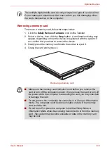
Page 101: ...ct under the cover and lift it off Removing the memory module cover 6 Lift one side of the insulator sheet and fit the module s connectors into the computer s connectors at about a 45 degree angle Press the module carefully to ensure a firm connection 7 Push the module down so it lies flat Latches on either side will click into place to secure the module Memory Module Cover Do not touch the connec...

Page 102: ...wing ways If there is only an error in Slot A repeatedly flashes orange twice then blue If there is only an error in Slot B repeatedly flashes orange then blue twice If there is an error in Slot A and in Slot B repeatedly flashes orange twice then blue twice In all instances you should shut down the computer and remove the incompatible module s Removing a memory module To remove the memory module ...

Page 103: ... portability of the computer with additional battery packs If you re away from an AC power source and your battery runs low you can replace it with a freshly charged battery Refer to Chapter 6 Power and Power Up Modes If you use the computer for a long time the memory modules will become hot In this case let the memory modules cool to room temperature before you replace them Or you will get burnt ...

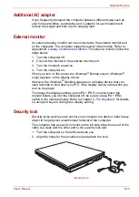
Page 104: ...creen Windows Logo appears on the display device However the Windows Desktop appears on a display device that you used last time to shut down your PC if the display device exists when you turn on the power To change the display settings press Fn F5 If you disconnect the monitor before you turn the computer off be sure to press Fn F5 to switch to the internal display Refer to Chapter 5 The Keyboard...

Page 105: ...e a printer attached print a copy of the screen using PrtSc The questions and procedures offered in this chapter are meant as a guide they are not definitive problem solving techniques Many problems can be solved simply but a few may require help from your dealer If you find you need to consult your dealer or others be prepared to describe the problem in as much detail as possible Preliminary chec...

Page 106: ...ll connecting cables are correctly and firmly attached Loose cables can cause erroneous or intermittent signals Do any indicators light Which ones What color are they Do they stay on or blink Write down what you see Do you hear any beeps How many Are they long or short Are they high pitched or low Is the computer making any unusual noises Write down what you hear Record your observations so you ca...

Page 107: ... computer tries to load the operating system depending on how the Boot Priority is set in the TOSHIBA HW Setup program If any of the following conditions are present the self test failed The computer stops and does not proceed to display information or messages except the TOSHIBA logo Random characters appear on the screen and the system does not function normally The screen displays an error mess...

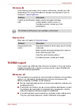
Page 108: ...emperature becomes too high the computer will automatically enter Hibernation Mode or Sleep Mode and shut down If the computer has reached room temperature and still does not start or if it starts but shuts down quickly contact your dealer AC power If you have trouble turning on the computer with the AC adaptor connected check the Battery indicator Refer to Chapter 6 Power and Power Up Modes for m...

Page 109: ...ch room temperature Unplug the AC adaptor and remove the battery to make sure the terminals are clean If necessary wipe them with a soft dry cloth dipped in alcohol Connect the AC adaptor and replace the battery Make sure it is securely seated Check the Battery indicator If it does not glow let the computer charge the battery for at least 20 minutes If the Battery indicator glows after 20 minutes ...

Page 110: ...letion procedures include Selecting Delete for a target file Putting files in the Recycle Bin and emptying the Recycle Bin Reformatting the media Reinstalling an operating system from the recovery CD ROM The procedures above delete only the initial part of the data used for file management This makes the file invisible to the operating system but the data can still be read by specialized utilities...

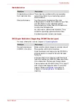
Page 111: ...numeric keypad overlay is not selected Press Fn F11 and try typing again Output to screen is garbled Make sure the software you are using is not remapping the keyboard Remapping involves reassigning the meaning of each key Refer to your software s documentation If you are still unable to use the keyboard consult your dealer Problem Procedure No display Press hot keys Fn F5 to change the display pr...

Page 112: ...sk Defragmenter As a last resort reformat the hard disk Then reload the operating system and other files If problems persist contact your dealer Problem Procedure You cannot access a CD DVD in the drive Make sure the drive s drawer is securely closed Press gently until it clicks into place Open the drawer and make sure the CD DVD is properly seated It should lie flat with the label facing up A for...

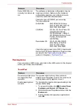
Page 113: ...rm2 Enhanced CD CDEXTRA Recordable CD CD R CD RW DVD R DVD R DL DVD RW DVD R DVD R DL DVD RW DVD RAM Check the region code on the DVD It must match that on the DVD Super Multi drive Region codes are listed in the Fixed optical media drives section in Chapter 2 The Grand Tour Problem Procedure Problem Procedure On screen pointer does not respond to Pad operation The system might be busy If the poin...

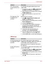
Page 114: ...k Sensitivity in the Select an item section on the left side of the screen 5 PalmCheck and Touch Sensitivity are displayed Click Touch Sensitivity 6 Move the slide bar for Touch Sensitivity to make an adjustment Click the OK button 7 Click the OK button on the Device Setting tab Problem Procedure On screen pointer does not respond to mouse operation The system might be busy If the pointer is shape...

Page 115: ...Set the pointer speed as required and click OK The mouse pointer moves erratically The mouse might be dirty Refer to your mouse documentation for instructions on cleaning If problems persist contact your dealer Problem Procedure Problem Procedure USB device does not work Check for a firm cable connection between the USB ports on the computer and the USB device Make sure the USB device drivers are ...

Page 116: ...tor and all peripheral devices 3 Remove the battery pack 4 Remove the memory module 5 Replace the battery pack and or connect the AC adaptor 6 Turn on the power If problems persist contact your dealer Problem Procedure No sound is heard Check the software volume settings Make sure the headphone connection is secure If problems persist contact your dealer Problem Procedure Monitor does not turn on ...

Page 117: ...re the tone or pulse selection in your communications application is set correctly Communication is cut off unexpectedly The computer will automatically cut off communication when connection with the carrier is not successful for a set time interval Try lengthening this time interval A CONNECT display is quickly replaced by NO CARRIER Check the error control setting in your communications applicat...

Page 118: ...w troubleshooting sections in the documentation for software and peripheral devices If a problem occurs when you are running software applications consult the software documentation for troubleshooting suggestions Call the software company s technical support for assistance Consult the dealer you purchased your computer and or software from They are your best sources for current information and su...

Page 119: ...ng Where to write If you are still unable to solve the problem and suspect that it is hardware related write to TOSHIBA at the location listed in the accomplanying warranty booklet or visit http www toshiba europe com on the internet ...

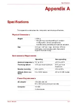
Page 120: ...ents manufacturing variability and options selected Size 310 w 227 d max 34 0 min 27 6 h millimetres not including parts that extend beyond the main body Operating Non operating Ambient temperature 5 C to 35 C 20 C to 65 C Thermal gradient 15 C per hour maximum 20 C per hour maximum Relative humidity 20 to 80 10 to 95 Altitude from sea level 0 to 3 000 meters 60 to 10 000 meters AC adaptor 100 240...

Page 121: ... 32bis V 34 V 90 V 92 103 212A V 17 V 29 V 27ter V 21 ch2 Communication Speed Data transmission and reception 300 1200 2400 4800 7200 9600 12000 14400 16800 19200 21600 24000 26400 28800 31200 33600 bps Data reception only with V 90 28000 29333 30666 32000 33333 34666 36000 37333 38666 40000 41333 42666 44000 45333 46666 48000 49333 50666 52000 53333 54666 56000 bps Fax 2400 4800 7200 9600 12000 1...

Page 122: ...ideo mode will run on any computer that supports the mode The computer s display controller supports all VGA modes the most widely used industry standards This series are equipped with Mobile Intel 965 Express display adaptors The video modes supported by the display chipset are shown in following tables Video modes The computer supports video modes defined in the tables below If your application ...

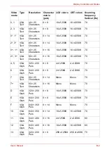
Page 123: ...6 of 256K 70 2 3 VGA Text 80 25 Characters 9 16 16 of 256K 16 of 256K 70 4 5 VGA Grph 320 200 Pels 8 8 4 of 256K 4 of 256K 70 6 VGA Grph 640 200 Pels 8 8 2 of 256K 2 of 256K 70 7 VGA Text 80 25 Characters 9 14 Mono Mono 70 7 VGA Text 80 25 Characters 9 16 Mono Mono 70 D VGA Grph 320 200 Pels 8 8 16 of 256K 16 of 256K 70 E VGA Grph 640 200 Pels 8 8 16 of 256K 16 of 256K 70 F VGA Grph 640 350 Pels 8...

Page 124: ...1024 768 256K 256K 256K 256K 60 75 85 100 1280 800 256K 256K 256K 256K 60 75 85 100 1280 1024 256K 256K 60 75 85 100 1600 1200 256K 256K 60 75 85 100 1920 1440 256K 256K 60 75 2048 1536 256K 256K 60 Some modes are not supported at LCD CRT simultaneous mode and LCD CRT Multi Monitor mode Some models only support a maximum resolution of 1024 768 ...

Page 125: ...5 100 1024 768 16M 16M 16M 16M 60 75 85 100 1280 800 16M 16M 16M 16M 60 75 85 100 1280 1024 16M 16M 60 75 85 100 1600 1200 16M 16M 60 75 85 100 1920 1440 16M 16M 60 75 2048 1536 16M 16M 60 Some modes are not supported at LCD CRT simultaneous mode and LCD CRT Multi Monitor mode Some models only support a maximum resolution of 1024 768 ...

Page 126: ...ersonalization Personalization Click Display Settings Display Properties Mobile Intel 965 Express Graphics Controller Properties The way to move to multi monitor Intel 965 Express Switch to Display Settings like shown in previous page Click Advanced Settings in Display Settings Click Graphics Properties in Intel Graphics Media Accelerator Driver for Mobile tab Select Displays Devices tab in Multip...

Page 127: ...m goes into Sleep Mode or Hibernation Mode you can switch to the LCD internal liquid crystal display display mode by pressing Fn F5 Under this environment however you may not return to the simultaneous LCD internal liquid crystal display display mode In these cases perform the following steps In Advanced feature of Display Settings Select the Display Devices tab click the icon indicating a display...

Page 128: ...rm the steps below First use the Screen resolution slide bar to select the 1280 800 resolution and then change the resolution to more than 1280 1024 and select Highest 32bit from the Color quality drop down menu Some models only support a maximum resolution of 1024 768 ...

Page 129: ...d local radio regulations may impose a number of limitations to the use of wireless communication equipment Form Factor Mini PCI TypeIII Compatibility IEEE 802 11 Standard for Wireless LANs Wi Fi Wireless Fidelity certified by the Wi Fi Alliance The Wi Fi CERTIFIED logo is a certification mark of the Wi Fi Alliance Network Operating System Microsoft Windows Networking Media Access Protocol CSMA CA...

Page 130: ...ons your Wireless LAN card may support a different set of 2 4 GHz channels Consult your Authorized Wireless LAN or TOSHIBA Sales office for information about the radio regulations that apply in the countries regions Wireless IEEE 802 11 Channels Sets Revision B and G 1 Factory set default channels 2 Refer to the sheet Approved Countries Regions for use for the countries regions that in which these...

Page 131: ...LAN Access Point When roaming between different access points the station can dynamically switch to another channel if required For Wireless LAN cards installed in wireless clients that operating in a peer to peer mode the card will use the default channel 10 In a Wireless LAN Access Point the Wireless LAN card will use the factory set default channel printed in bold unless the LAN Administrator s...

Page 132: ...ited States and Canada plug configuration must be a 2 15P 250 V or 1 15P 125 V as designated in the U S National Electrical code handbook and the Canadian Electrical Code Part II Length Minimum 1 7 meters Wire size Minimum 0 75 mm2 Current rating Minimum 2 5 amperes Voltage rating 125 or 250 VAC depending on country region s power standards U S and Canada UL listed and CSA certified No 18 AWG Type...

Page 133: ...s The following illustrations show the plug shapes for the U S A and Canada the United Kingdom Australia and Europe USA and Canada UL approved CSA approved United Kingdom BS approved Australia AS approved Europe Approved by the appropriate agency ...

Page 134: ...Performance Legal Footnotes CPU performance in your computer product may vary from specifications under the following conditions use of certain external peripheral products use of battery power instead of AC power use of certain multimedia computer generated graphics or video applications use of standard telephone lines or low speed network connections use of complex modeling software such as high...

Page 135: ... bit computing requires that the following hardware and software requirements are met 64 bit Operating System 64 bit CPU Chipset and BIOS Basic Input Output System 64 bit Device drivers 64 bit applications Certain device drivers and or applications may not be compatible with a 64 bit CPU and therefore may not function properly A 32 bit version of the operating system is preinstalled on your comput...

Page 136: ...omputer operating system however reports storage capacity using powers of 2 for the definition of 1 GB 230 1 073 741 824 bytes and therefore shows less storage capacity Available storage capacity will also be less if the product includes one or more pre installed operating systems such as Microsoft Windows and or pre installed software applications or media content Actual formatted capacity may va...

Page 137: ...design and configuration and client design and software hardware configurations 54Mbps is the theoretical maximum speed under the IEEE802 11 a b g standard The actual transmission speed will be lower than the theoretical maximum speed Copy Protection Applicable copy protection standards included in certain media may prevent or limit recording or viewing of the media Images All images are simulated...

Page 138: ...form to the address below To register the theft online please follow these procedures Visit http www toshiba europe com on the Internet In the product area choose Computer Systems In the Computer Systems page open the Support Downloads menu and choose the Stolen Units Database option Your entries are used to track your computer at our service points Always take care of your computer and try to pre...

Page 139: ...Technical Service and Support Leibnizstr 2 93055 Regensburg Germany Fax number 49 0 941 7807 921 Owner s details Country stolen Machine type e g U300 Model number e g PSA50 YXT Serial number e g 12345678G Date stolen Year Month Day Last name first name Company Street Postal Code City Country Phone Fax ...

Page 140: ...OS basic input output system CD ROM Compact Disc Read Only Memory CD RW Compact Disc Read Write CMOS complementary metal oxide semiconductor CPU central processing unit CRT cathode ray tube DC direct current DDC display data channel DMA direct memory access DOS disk operating system DVD digital versatile disc ECP extended capabilities port FIR fast infrared HDD hard disk drive IDE integrated drive...

Page 141: ... adaptor modifies the power from a wall outlet for use by the computer This term also refers to the add in circuit cards that control external devices such as video monitors and magnetic tape devices allocate To assign a space or function for a specific task alphanumeric Keyboard characters including letters numbers and other symbols such as punctuation marks or mathematical symbols alternating cu...

Page 142: ...number has a value of 1 the next a value of 2 then 4 8 16 and so on For example the binary number 101 has a value of 5 See also ASCII BIOS Basic Input Output System The firmware that controls data flow within the computer See also firmware bit Derived from binary digit the basic unit of information used by the computer It is either zero or one Eight bits is one byte See also byte board A circuit b...

Page 143: ...es See also CD ROM character Any letter number punctuation mark or symbol used by the computer Also synonymous with byte chassis The frame containing the computer chip A small semiconductor containing computer logic and circuitry for processing memory input output functions and controlling other chips CMOS Complementary Metal Oxide Semiconductor An electronic circuit fabricated on a silicon wafer ...

Page 144: ...ions CRT Cathode Ray Tube A vacuum tube in which beams projected on a fluorescent screen producing luminous spots An example is the television set cursor A small blinking rectangle or line that indicates the current position on the display screen D data bits A data communications parameter controlling the number of bits binary digits used to make up a byte If data bits 7 the computer can generate ...

Page 145: ...e volumes of data The DVD ROM drive uses a laser to read data from the disc DVD ROM A Digital Versatile Disc Read Only Memory is a high capacity high performance disc suitable for play back of video and other high density files The DVD ROM drive uses a laser to read data from the disc E echo To send back a reflection of the transmitted data to the sending device You can display the information on ...

Page 146: ...cs Drawings pictures or other images such as charts or graphs to present information H hard disk drive HDD An electromechanical device that reads and writes a hard disk See also hard disk hard disk A non removable disk usually referred to as drive C The factory installs this disk and only a trained engineer can remove it for servicing Also called fixed disk hardware The physical electronic and mec...

Page 147: ... specifically to connect one system or device to another 2 To physically connect one system or device to another to exchange information 3 The point of contact between user the computer and the program for example the keyboard or a menu interrupt request A signal that gives a component access to the processor IrDA 1 1 An industry standard that enables cableless infrared serial data transfer at spe...

Page 148: ...ce that displays a list of options on the screen Also called a screen microprocessor A hardware component contained in a single integrated circuit that carries out instructions Also called the central processing unit CPU one of the main parts of the computer mode A method of operation for example the boot mode Sleep Mode or the Hibernation Mode modem Derived from modulator demodulator a device tha...

Page 149: ...rial port of internal modem or 4 stored on some magnetic media P parity 1 The symmetrical relationship between two parameter values integers both of which are either on or off odd or even 0 or 1 2 In serial communications an error detection bit that is added to a group of data bits making the sum of the bits even or odd Parity can be set to none odd or even password A unique string of characters u...

Page 150: ...eed memory within the computer circuitry that can be read or written to restart Resetting a computer without turning it off also called warm boot or soft reset See also boot RGB Red green and blue A device that uses three input signals each activating an electron gun for a primary additive color red green and blue or port for using such a device See also CRT RJ11 A modular telephone jack RJ45 A mo...

Page 151: ... disk Also called an operating system disk T terminal A typewriter like keyboard and CRT display screen connected to the computer for data input output TFT display A liquid crystal display LCD made from an array of liquid crystal cells using active matrix technology with thin film transistor TFT to drive each cell TouchPad A pointing device integrated into the TOSHIBA computer palm rest TTL Transi...

Page 152: ...play 1 5 automatic power off 1 8 brightness decreases 5 3 brightness increases 5 4 controller 1 5 opening 3 4 Display controller B 1 E Equipment checklist 1 1 Express Card 8 1 inserting 8 2 removing 8 2 F Floppy disk using 4 4 Fn Esc sound mute 5 3 Fn F1 instant security 5 3 Fn F2 power save mode 5 3 Fn F3 Sleep Mode 5 3 Fn F4 hibernation 5 3 Fn F5 display selection 5 3 Fn F6 Display Brightness de...

Page 153: ...1 7 4 17 connecting 4 19 disconnecting 4 20 properties menu 4 17 region selection 4 17 Monitor external 1 6 8 10 P Ports 1 6 external monitor 1 6 USB 1 6 Power conditions 6 1 hibernation mode 3 7 indicator 6 2 panel power on off 1 8 6 13 shut Down mode Boot mode 3 5 Sleep Mode 3 6 system Auto Off 6 13 turning off 3 5 turning on 3 5 Power up modes 6 13 Problems AC power 9 4 analyzing 9 2 Battery 9 ...

Page 154: ...atic 1 8 Soft keys emulating keys on enhanced keyboard 5 2 ScrLock 5 3 Sound System 1 6 4 16 headphone jack 1 6 microphone jack 1 6 mute hot keys 5 3 T TOSHIBA ConfigFree 1 11 TOSHIBA Disc Creator 1 10 TOSHIBA Theft Registration F 2 Touch Pad 1 6 location 2 6 using 4 1 U USB 1 6 V Video modes B 1 Video RAM 1 3 W Wireless communication switch 4 21 indicator 4 22 Wireless LAN 1 7 using 4 20 ...

Reviews: