29
Advanced playback
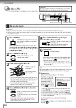
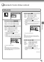
Playing in Random Order
You can play titles, chapters within a title, or tracks in random order.
(Random playback)
Playing titles, chapters or tracks in random order
Press RANDOM.
Each time you press the RANDOM
button, the random playback mode
changes as follows.
If you press the RANDOM button
during playback, the DVD video
player automatically starts random
playback after finishing the current
title, chapter or track.
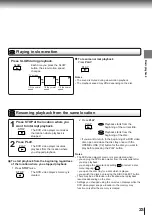
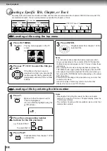
Press PLAY.
The DVD video player starts random
playback.
Press the PLAY button within about
5 seconds after you press the
RANDOM button.
2
1
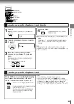
To resume normal playback
Press CLEAR.
Notes
• Some discs may not permit random playback operation.
• You cannot use the random playback function in conjunction
with the memory playback function.
Title:
1
Chapter:
3
Title:
2
Chapter:
2
Title:
3
Chapter:
1
CLEAR
2
1
Chapter Random
Title Random
Track Random
Random Off
Plays the chapters
within the current title
in random order.
Plays the titles within
the current disc in
random order.
Plays the tracks within
the current disc in
random order.
Resumes normal
playback.
RANDOM
PLAY
DVD
VCD
CD
DVD
DVD
VCD
CD
CLEAR
Chapter Random
Summary of Contents for SD-2050
Page 1: ...DVD VIDEO PLAYER SERVICE MANUAL May 2000 s FILE NO 810 200005 SD 2050 DIGITAL VIDEO ...
Page 5: ...SECTION 1 GENERAL DESCRIPTIONS SECTION 1 GENERAL DESCRIPTIONS 1 OPERATING INSTRUCTIONS ...
Page 51: ...47 Others Memo ...
Page 80: ...4 2 Power Supply Block Diagram Fig 3 4 2 ...
Page 82: ...Fig 3 4 5 4 3 3 Front Display Power Switch Block Diagram ...
Page 84: ...Fig 3 4 7 4 4 2 Logical System Block Diagram ...
Page 85: ...4 5 Output Block Diagram Fig 3 4 8 ...
Page 88: ...10 1 3 4 A B C D E G 2 5 6 7 8 9 F Fig 3 5 3 5 2 Front Display Power Switch Circuit Diagram ...
Page 95: ...Fig 3 5 5 5 3 2 Main Circuit Diagram ...
Page 96: ...5 3 2 Main Circuit Diagram ...
Page 97: ......
Page 98: ......
Page 99: ......
Page 100: ......
Page 101: ......
Page 102: ......
Page 103: ...Fig 3 5 5 ...
Page 105: ...Fig 3 5 6 10 1 3 4 A B C D E G 2 5 6 7 8 9 F 11 H 5 4 Output Circuit Diagram ...
Page 115: ...10 1 3 4 A B C D E G 2 5 6 7 8 9 F Fig 3 6 6 EU01 Main PC Board Top pattern character symbol ...
Page 125: ......


