background image

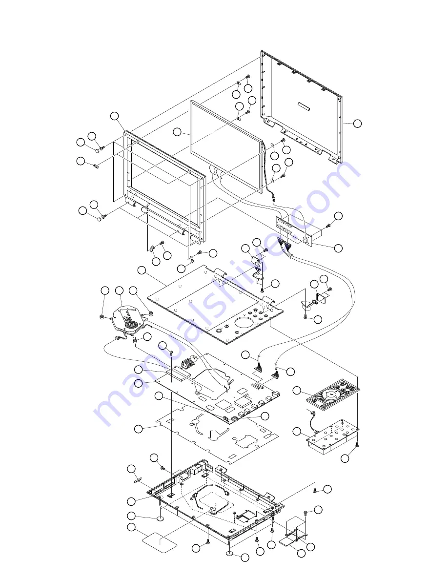
CHASSIS ASSEMBLY

SD-P2900SN

a

a

1  *

2

3  *

6

25

25

4

25

5

25

8

25

9

25

9

25

7

7

18

19

25

25

10

12

25

16

13

21

25

25

25

25

25

25

22

23

17

20

24

24

26

14

15

12

11

12

8

25

4

25

25

25

25

25

25

25

25

*Note: There are 6 picks between the side of Top Panel (1) and LCD Mask (3).
Damage to Top Panel and LCD Mask may occur if removing the picks by metal tool.
(i.e. screwdriver) Please use plastic tool of same strength to remove the picks. 

Summary of Contents for SD-P2900SN

Page 1: ... above model is classified as a green product 1 as indicated by the underlined serial number This Service Manual describes replacement parts for the green product When repairing this green product use the part s described in this manual and lead free solder 2 For 1 and 2 see the next page ...

Page 2: ...ement of parts is not only confined to manufacture The same green parts used in manufacture must also be used as replacement parts 2 LEAD FREE SOLDER This product is manufactured using lead free solder as a part of a movement within the consumer products industry at large to be environmentally responsible Lead free solder must be used in the servicing and repair of this product WARNING This produc...

Page 3: ... it operates properly after replacement if it was subject to electrostatic discharge during replacement its life might be shortened When replacing use a conductive mat soldering iron with ground wire etc to protect the laser diode from damage by static electricity And also the LSI and IC are same as above Soldering iron with ground wire or ceramic type Ground conductive wrist strap for body Conduc...

Page 4: ...xists the fault must be located and corrected Repeat the above test with the DVD VIDEO PLAYER power plug reversed NEVER RETURN A DVD VIDEO PLAYER TO THE CUSTOMER WITHOUT TAKING NECESSARY CORRECTIVE ACTION READING SHOULD NOT EXCEED 0 3V DVD VIDEO PLAYER AC OUTLET AC VOLTMETER Test all exposed metal Voltmeter Hook up for Leakage Current Check 0 15uF 150V AC 1500 10W 5000 per volt or more sensitivity...

Page 5: ...TV1 XS4 XS3 XS5 1 2 3 4 1 2 3 4 XS2 BATTERY THM GND GND BATTERY 30 29 28 27 26 25 24 23 22 21 20 19 18 17 16 15 14 13 12 11 10 9 8 7 6 5 4 3 2 1 GND R2 R3 R4 R5 R6 R7 GND V2T V4T V6T V8T V10T A VDD 8 8V GND VCOM GND V13T VGH V14T VGL V12T LCD VDD GND GND STV1 GCLK OE STV2 POL 30 29 28 27 26 25 24 23 22 21 20 19 18 17 16 15 14 13 12 11 10 9 8 7 6 5 4 3 2 1 30 29 28 27 26 25 24 23 22 21 20 19 18 17 ...

Page 6: ... 0 6 1 V L 9 2 H K M A R D S M 4 6 HY57V641620ETP 7 C UPD5600A R O T I N O M T F T P M A O I D U A 8 5 5 4 C T U P M A R E K A E P S 2 1 2 0 A P T T U O O E D I V T U O O I D U A T U O E N O H P T U O L R E K A E P S T U O R R E K A E P S L R V 5 R E V I R D V 5 V 5 V 3 3 V 8 1 V 5 O I D U A VGH VGL LCD VDD AVDD8V8 2 5V V 3 3 T U O C Y z H M 7 2 V 5 DV23FA m s i n a h c e m U P R E V I R D 8 8 8 5...

Page 7: ...r supply cable If the cable is not the supplied one replace it with the supplied cable and turn on the power again If the power supply cable is good the AC adapter may be defective If the LED does not light after replacing check the following items 2 Check the AC adapter If the AC adapter is not the supplied one replace it with the supplied AC adapter and turn on the power If the AC adapter is goo...

Page 8: ...D mask and plate of the LCD unit and check the following z Check the connector of the harness replace the LCD PCB or the LCD unit z If the connectors are good replace the LCD PCB or the LCD unit 3 Check the lighting of LCD If the LCD does not light separate the DVD player into the top assembly and bottom assembly and check the harness and check the connectors on the main PCB If the connector is br...

Page 9: ... main PCB is defective Replace the DVD drive or the main PCB The DVD drive works but the initializing operation of the optical pick up lens does not start the optical pick up lens operates twice or abnormal noise sound The DVD drive is defective Replace the DVD drive 1 4 The operation of the DVD player stops at initializing display If the DVD player does not work after the initializing screen is d...

Page 10: ...B or speaker 1 7 No image or sound comes out from the external output If any image or sound is output from the TV connected by the external cable replace the main PCB NOTE Before this test make sure the drive works 1 8 No sound comes out from the headphones If no sound comes out from the headphones replace the main PCB 1 9 No image or sound is output by the external input If any image or sound is ...

Page 11: ... 5 3 S S 1 2 2 B C N 0 0 1 2 2 B C N 0 0 1 5 D V N 2 6 Z T S 5 D V N 2 6 Z T S 1 3 C M N F p 3 3 1 3 C M N F p 3 3 R53 15 4K 1 R53 15 4K 1 K 3 3 1 5 2 R K 3 3 1 5 2 R 2 3 C F p 0 5 1 2 3 C F p 0 5 1 6 8 R K 1 6 8 R K 1 K 0 1 3 2 R K 0 1 3 2 R F n 1 6 2 1 C F n 1 6 2 1 C 4 3 D V N 2 6 Z T S 4 3 D V N 2 6 Z T S 1 2 C M N F p 3 3 1 2 C M N F p 3 3 2 1 R K 0 1 2 1 R K 0 1 5 C F p 0 5 1 5 C F p 0 5 1 3...

Page 12: ... C P 0 0 1 1 2 3 9 5 D V 8 9 2 1 A T K 9 5 D V 8 9 2 1 A T K 5 6 2 C N 0 1 5 6 2 C N 0 1 K 2 2 9 R K 2 2 9 R 8 3 R K 2 8 3 R K 2 6 5 4 3 2 1 3 S X 0 9 6 0 1 6 2 3 5 3 S X 0 9 6 0 1 6 2 3 5 1 2 3 2 1 D V 8 9 2 1 A T K 2 1 D V 8 9 2 1 A T K 0 5 R K 2 0 5 R K 2 2 W S 0 2 S D 2 W S 0 2 S D 9 5 R 1 K 1 9 5 R 1 K 1 R 0 2 2 3 9 2 R R 0 2 2 3 9 2 R 5 5 R R 0 5 5 R R 0 T 3 2 T 2 2 F 1 2 M F H 6 1 C N 5 1 D...

Page 13: ... 4 R C D 1 4 5 E Q 5 R C D 2 4 6 E Q 6 R C D 3 4 7 E Q 7 R C D 4 4 8 E Q 0 B C D 8 4 9 E Q 1 B C D 9 4 0 1 E Q 2 B C D 0 5 1 1 E Q 3 B C D 1 5 2 1 E Q 4 B C D 2 5 3 1 E Q 5 B C D 3 5 4 1 E Q 6 B C D 4 5 5 1 E Q 7 B C D 5 5 6 1 E Q 0 Y D 9 5 7 1 E Q 1 Y D 0 6 8 1 E Q 2 Y D 1 6 9 1 E Q 3 Y D 2 6 0 2 E Q 4 Y D 3 6 1 2 E Q 5 Y D 4 6 2 2 E Q 6 Y D 5 6 3 2 E Q 7 Y D 6 6 2 H T S E D 1 7 H K L C K C L L 2...

Page 14: ...2 D V 1 0 6 D S 2 V 6 1 F u 0 1 5 2 C V 6 1 F u 0 1 5 2 C K 5 1 7 7 R K 5 1 7 7 R K 1 3 6 R K 1 3 6 R 3 3 0 6 R 3 3 0 6 R 0 1 7 0 1 R 0 1 7 0 1 R 1 B 1 D N G 2 0 B 3 A 4 C C V 5 S 6 9 N 7 5 1 3 C V L 4 7 9 N 7 5 1 3 C V L 4 7 K 0 0 1 9 9 R K 0 0 1 9 9 R 1 0 6 1 L 1 0 6 1 L K 0 1 0 3 1 R K 0 1 0 3 1 R 0 1 D V N 2 6 Z T S 0 1 D V N 2 6 Z T S 6 6 C F p 0 6 1 6 6 C F p 0 6 1 1 2 3 4 5 7 8 S J 0 4 1 0 ...

Page 15: ... R 0 7 4 5 3 2 R 5 7 3 1 2 R 5 7 3 1 2 R C N 8 0 2 R C N 8 0 2 R 0 7 4 1 4 2 R 0 7 4 1 4 2 R R217 10K R217 10K 1 2 3 4 5 6 7 8 9 N R 4 3 3 9 N R 4 3 3 1 2 2 3 1 C V 6 1 F u 0 1 2 3 1 C V 6 1 F u 0 1 K 2 6 9 1 R K 2 6 9 1 R 0 7 4 2 3 2 R 0 7 4 2 3 2 R 1 2 3 4 5 3 3 D V 5 0 7 C S 3 3 D V 5 0 7 C S R199 10K R199 10K 1 6 B C n 0 0 1 1 6 B C n 0 0 1 C N 9 0 2 R C N 9 0 2 R 1 2 5 6 B C N 0 0 1 5 6 B C N...

Page 16: ... D V 5 0 M 9 2 D M S 3 2 2 T O S F n 1 3 0 1 C F n 1 3 0 1 C 6 3 1 C V 6 1 F u 0 1 6 3 1 C V 6 1 F u 0 1 5 6 7 8 4 B 2 N A P O 8 5 5 4 M J N B 2 N A P O 8 5 5 4 M J N F u 1 0 3 1 B C F u 1 0 3 1 B C K 5 7 6 R K 5 7 6 R 7 9 C F p 0 0 1 7 9 C F p 0 0 1 0 9 C V 6 1 F u 0 1 0 9 C V 6 1 F u 0 1 8 1 1 C V 6 1 F u 0 0 1 8 1 1 C V 6 1 F u 0 0 1 5 4 1 C F p 0 0 1 5 4 1 C F p 0 0 1 0 1 1 C V 6 1 F u 0 0 1 0...

Page 17: ...C F u 1 0 3 C V 6 1 F u 0 1 3 C V 6 1 F u 0 1 1 3 R 0 1 3 R 0 T 7 V T 7 V 9 9 V A B 1 D V 9 9 V A B 1 D V 4 3 C F u 1 0 4 3 C F u 1 0 F u 1 0 5 C F u 1 0 5 C T 3 V T 3 V 6 2 R 0 0 3 6 2 R 0 0 3 3 B C F u 1 0 3 B C F u 1 0 7 C V 6 1 F u 0 1 7 C V 6 1 F u 0 1 5 2 R 3 3 5 2 R 3 3 1 2 K 5 1 6 5 R K 5 1 6 5 R 9 9 V A B 7 1 D V 9 9 V A B 7 1 D V 7 R 0 0 2 7 R 0 0 2 6 2 C V 6 1 F u 0 1 6 2 C V 6 1 F u 0 ...

Page 18: ...A B C D E G 2 F 1 3 4 5 6 7 8 9 10 MAIN BOARD DIAGRAM TOP SIDE ...

Page 19: ...A B C D E G 2 F 1 3 4 5 6 7 8 9 10 MAIN BOARD DIAGRAM BOTTOM SIDE ...

Page 20: ...A B C D E G 2 F 1 3 4 5 6 7 8 9 10 LCD BOARD DIAGRAM ...

Page 21: ... 25 25 25 25 25 22 23 17 20 24 24 26 14 15 12 11 12 8 25 4 25 25 25 25 25 25 25 25 Note There are 6 picks between the side of Top Panel 1 and LCD Mask 3 Damage to Top Panel and LCD Mask may occur if removing the picks by metal tool i e screwdriver Please use plastic tool of same strength to remove the picks ...

Page 22: ...SD P2900SN PACKING ASSEMBLY 28 30 27 29 32 33 31 35 34 ...

Page 23: ...6 e27035 Function button 19 AH302427 e22802 Function PCB 20 AH302428 e27036 Bottom cover ass y 21 AH302429 eb45726 Bottom shield 22 AH301619 eb32320h Battery slot slider 23 AH301620 eb32295h Battery slot holder 24 AH301617 eb40826 Bottom cover pad 25 AH302430 e27037 Screw kit 26 AH302431 es13187 Rating label without serial number 27 AH302432 e25130 Battery pack with the rating label SD PBP100S 28 ...

Page 24: ...1 1 SHIBAURA 1 CHOME MINATO KU TOKYO 105 8001 JAPAN ...

Reviews: