background image

37

Troubleshooting

in Test Operation

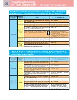
In checking the number of connected outdoor units and connected indoor unit after address 

setup, a lower number of connected units is displayed.


(There are outdoor/indoor units that do not operate in a test operation.)

s

e

r

u

s

a

e

m

r

e

t

n

u

o

C

e

s

u

a

C

s

u

t

a

t

S

The number of 

connected

outdoor units is 

too few.

Miswiring of communication lines between outdoor units

or an unconnected wire ( Fig. 4). 

(Address setup operation finished without recognizing a 

miswired follower unit.)

After modification of wiring, set up the addresses again and 

check the number of connected outdoor units.

The number of 

connected indoor 

units is too few.

Miswiring of communication lines between indoor units

or an unconnected wire. (Fig 5)

(Address setup operation finished without recognizing a

miswired indoor unit.)

After modification of wiring, set up the addresses again and 

check the number of connected indoor units.

The number of 

outdoor units 

connected to a 

group is too few in 

group operation 

from an indoor 

remote controller.

The indoor remote controller is not connected with wire.

Miswiring of the indoor remote controller

Using the main indoor remote controller connected to a group, 

start a test operation, specify the unit that is not operating (the 

unit not connected to the group), and then check the wiring.

Indoor remote controller communication circuit trouble

If 220-240 V is incorrectly applied to the remote 

controller terminal, the remote controller communication 

circuit fails.


Using the main indoor remote controller connected to a group,

start a test operation and then specify the unit that is not

operating (the unit not connected to the group). Remove the

Faston connect terminal connected to remote controller

terminals A/B, and check the voltage. If voltage is not applied

(normally 15 to18 V), replace the PC board.

<Cooling, Heat pump type>

Summary of Contents for SMMS-e

Page 1: ...gerant Piping Refrigerant Piping Systematic Address Setup Test Operation Troubleshooting in Test Operation Monitoring Function NFC Wave Tool Refrigerant Leakage Detection Service Support Function Backup Operation Outdoor Interface P C board Leaking Clogging Troubleshooting ...

Page 2: ...refrigerant charge amount at site 1 2 3 1 Compensation by system HP Table 1 2 Additional refrigerant charge amount Indoor unit Table 2 3 Real length of liquid pipe Additional refrigerant charge amount per liquid pipe 1 m Table 3 1 2 For HT8P E model Table 1 System Combination Charged refrigerant kg Compensation by System HP HP HP kg Standard model 8 8 11 5 3 5 10 10 11 5 3 5 12 12 11 5 1 5 14 14 1...

Page 3: ...3 Real length of liquid pipe Additional refrigerant charge amount per liquid pipe 1 m Table 3 1 2 Table 1 Space saving model High efficiency High Diversity model System Combination Charged refrigerant Compensation by System HP System Combination Charged refrigerant by System HP HP HP kg kg HP HP kg kg 8 8 10 5 3 5 20 10 10 21 7 0 7 0 12 10 21 12 12 12 31 5 32 5 12 5 14 12 12 10 5 14 14 12 33 5 8 5...

Page 4: ...nch Li 90 m Y shaped branching joint Indoor unit Height difference between indoor units H2 40 m s t i n u 3 o t p U n o i t a n i b m o c t i n u r o o d t u O Note 1 D is outdoor unit furthest from the 1st branch and j is the indoor unit furthest from the 1st branch 2 If the height difference H1 between indoor and outdoor unit exceeds 3 m set 65 m or less 3 If the max combined outdoor unit capaci...

Page 5: ... U n o i t a n i b m o c t i n u r o o d t u O Note 1 D is outdoor unit furthest from the 1st branch and j is the indoor unit furthest from the 1st branch 2 If the height difference H1 between indoor and outdoor unit exceeds 3 m set 65 m or less 3 If the max combined outdoor unit capacity is 54HP or more then max equivalent length is 70 m or less real length is 50 m or less 4 If the height differe...

Page 6: ... a b c d e f g h i j 34HP or more 1000m 6 Farthest piping Length L 1 Equivalent length 235m LA L1 L3 L4 L5 L6 j Real length 190m Equivalent length of farthest piping from 1st branching Li 1 90m 2 L3 L4 L5 L6 j Equivalent length of farthest piping between outdoor units LO 25m LA Lc LA Lb Max equivalent length of main piping Equivalent length 120m 3 L1 Real length 100m 3 Max equivalent length of out...

Page 7: ...nce pipes Ø9 5 1 Outdoor unit connecting pipes 3 Main piping 8 Outdoor unit connection piping kit For linking of outdoor units 4 Branching pipe First branch Y shape branching joint 7 Branching header 6 Y shaped branching joint 5 Indoor unit connecting pipe Indoor unit Indoor unit Cooling Heat pump type Selection of refrigerant piping ...

Page 8: ...ame Selection of pipe size Remarks 1 Outdoor unit Outdoor unit connection piping kit Outdoor unit connecting pipe Connecting pipe size of outdoor unit Type Gas side Liquid side MMY MAP0806 Ø19 1 Ø12 7 MMY MAP1006 Ø22 2 Ø12 7 MMY MAP1206 Ø28 6 Ø12 7 MMY MAP1406 Ø28 6 Ø15 9 MMY MAP1606 Ø28 6 Ø15 9 MMY MAP1806 Ø28 6 Ø15 9 Same as connecting pipe size of the outdoor unit 2 Between Outdoor unit connect...

Page 9: ...26 equivalent to HP and you use a branching header for the first branching section use a RBM HY2043E or RBM HY2083E regardless of the total capacity codes of outdoor units at downstream side In addition you cannot use a branching header for the first branching section when the total capacity codes of all outdoor units are over 26 equivalent to HP 8 Branching section Outdoor unit connection piping ...

Page 10: ...xchanger Left side Main heat exchanger PMV1 4 way valve High pressure sensor Low pressure sensor Oil separator Fusible plug Liquid Tank Accumulator High pressure switch High pressure switch Compressor 1 Inverter Oil Header Liquid side Service valve Gas side Service valve Balance pipe Service valve Sub cool heat exchanger SV SV52 Reducer FP Compressor 2 Inverter SV Solenoid valve Capillary tube Che...

Page 11: ...t exchanger Right side Sub heat exchanger Left side Sub heat exchanger PMV1 PMV3 4 way valve High pressure sensor Low pressure sensor Oil separator Accumulator Liquid Tank Liquid side Service valve Gas side Service valve Balance pipe Service valve Oil Header High pressure switch High pressure switch Reducer Fusible plug FP Sub cool heat exchanger Compressor 1 Inverter Compressor 2 Inverter SV Sole...

Page 12: ...ft side Main heat exchanger Right side Sub heat exchanger Left side Sub heat exchanger PMV1 PMV3 4 way valve High pressure sensor Low pressure sensor Oil separator Liquid Tank Oil Header High pressure switch High pressure switch Sub cool heat exchanger Fusible plug FP Liquid side Service valve Gas side Service valve Balance pipe Service valve SV Solenoid valve Capillary tube Check valve Check join...

Page 13: ... unit Compressor case heater Compressor 1 Connector CN331 White Compressor 2 Connector CN332 Blue 1 Prevents liquid accumulation to compressor Accumulator case heater Connector CN334 Red 1 Prevents liquid accumulation to accumulator PMV1 Connector CN300 White PMV3 Connector CN302 Blue 1 Super heat control function in heating operation 2 Liquid line shut down function while follower unit stops 3 Su...

Page 14: ...of a wired remote controller Check that a frame as shown in the following figure at left is displayed on the LC display section of the remote controller If no frame is displayed as shown in the above figure at right the remote controller does not have a normal supply of power check the following items Check the power supply of the indoor unit Check the cabling between the indoor unit and the remot...

Page 15: ...rt Confirm the items in Address Setup Procedure and then set up the address according to the operation procedure Be careful to note that the setup operation may differ in group control and central control systems Note The address cannot be set up if switches are not operated s t n e t n o c k c e h c d n a n o i t a r e p O m e t I 5 Display check after setup After address setup U1 is displayed on...

Page 16: ...rol connect a relay connector between U1 U2 and U3 U4 terminals REQUIREMENT When 2 or more refrigerant lines are controlled as a group be sure to turn on all the indoor units in the group before setting addresses If you set the unit addresses of each line separately each line s header indoor unit is set separately In that case the CODE No L03 Indoor header unit overlap is indicated as running star...

Page 17: ...es as a group System wiring diagram Outdoor Indoor Indoor Indoor Indoor Outdoor Remote controller Group control SW06 SW07 SW09 SW10 SW11 SW12 SW13 SW14 1 2 3 4 1 2 3 4 1 2 3 4 1 2 3 4 1 2 3 4 1 2 3 4 1 2 3 4 1 2 3 4 Line address switches on the outdoor interface PC board O switch on switch off SW13 SW14 1 1 2 3 4 5 6 7 8 9 10 11 12 13 14 O O O O O O O O O O O O O O O O O O O O O O O O O 2 3 4 1 2 ...

Page 18: ...rface P C board of the header outdoor unit indicates U 1 L08 U 1 flash 5 Push SW 15 to start the automatic address setting It may take up to 10 minutes normally about 5 minutes to complete one line s setting 6 The 7 segment display indicates Auto 1 Auto 2 Auto 3 After the indication U 1 U 1 flash starts flashing on the display When the flashing stops and U 1 U 1 light remains lit on the display th...

Page 19: ... address of header unit 8 1 2 SW30 SW30 bit switch ON The smallest line adress of header unit 4 6 5 8 After completing address setting of all systems turn off DIPswitch 2 of SW30 on the interface P C boards of all the header outdoor units connected to the same central control except the unit that has the lowest address For unifying the termination of the wiring for the central control of indoor an...

Page 20: ...ess 1 1 2 2 3 Indoor unit address 1 2 1 2 1 Group address 0 0 1 2 0 A U1 U2 U3 U4 U3 U4 U3 U4 U3 U4 U3 U4 U5 U6 U1 U2 U5 U6 U1 U2 U5 U6 U1 U2 U5 U6 U1 U2 2 U 1 U 2 U 1 U 2 U 1 U 2 U 1 U 2 U 1 U U5 U6 B A B A B A B A B Central remote controller Relay connector Relay connector Relay connector Header unit Header unit Header unit Follower unit Follower unit Remote controller Remote controller Remote c...

Page 21: ...to 14 Using the TIME buttons set up the central control address 15 Push SET button OK when display goes on 16 Push the TEST button Setup is finished Setting up blinks when Setting up goes off operation is possible 17 Return to the original wiring over remote controllers Group address Individual 0000 Header unit 0001 Follower unit 0002 Wiring example for 2 refrigerant lines Line 1 Line 2 Line 1 Lin...

Page 22: ...ach refrigerant line After that set up the central control address For central control address setup refer to the installation manual of the central control devices Confirming the indoor unit addresses and the position of an indoor unit using the remote controller Confirming the numbers and positions of indoor units To see the indoor unit address of an indoor unit which you know the position of Wh...

Page 23: ... on UNIT No on the LCD display The fans and louvers of all the indoor units in the group are activated 2 Push the UNIT LOUVER button left side of the button Each time you push the button the indoor unit numbers are indicated one after another The first indicated unit number is the address of the header unit Only the fan and louvers of the indicated indoor unit are activated 3 Push the TEST button ...

Page 24: ...or more than 4 seconds At first the line 1 and CODE No Address Change are indicated on the LCD display Select an outdoor unit 2 Push UNIT LOUVER the left side of the button and SWING FIX buttons repeatedly to select a system address 3 Push the SET button to confirm the system address selection The address of an indoor unit connected to the selected refrigerant line is indicated on the LCD display ...

Page 25: ...nits are controlled in a group The fan and louvers of the selected indoor unit are activated The fan of the selected indoor unit is turned on 3 Push the TEMP buttons repeatedly to select for CODE No 4 Push the TIME buttons repeatedly to change the value indicated in the SET DATA section to that you want 5 Push the SET button 6 Push the UNIT LOUVER button left side of the button repeatedly to selec...

Page 26: ...to the selected refrigerant line is indicated on the LCD display and the fan and louvers of the unit are activated At first the current indoor unit address is displayed in SET DATA No system address is indicated 4 Push the TIME buttons repeatedly to change the value of the indoor unit address in SET DATA Change the value in SET DATA to that of a new address 5 Push the SET button to confirm the new...

Page 27: ...ate the interface P C board on the header outdoor unit of the refrigerant line as follows 3 Confirm that the 7 segment display indicates A d c L and set SW01 SW02 and SW03 to 1 1 1 respec tively 4 After a time U 1 L08 appears on the 7 segment display if the address clearing has been completed successfully If the 7 segment display indicates A d n G the outdoor unit may still connected with other re...

Page 28: ...tdoor header unit side Turn off the power and then execute the operation 3 Turn on the indoor outdoor power for the refrigerant line for which an address is to be set up After approximately 1 minute check that U 1 is displayed on the 7 segment display 4 Execute the following operation on the interface PC board of the header unit is counted and displayed on the 7 segment display 5 When is displayed...

Page 29: ...wer unit C Outdoor unit Indoor unit Remote controller Remote controller Remote controller k c e h C s m e t i k c e h c n i a M Relay connector 1 Is the relay connector of the header unit connected after address setup 2 Is the relay connector of the follower unit disconnect Terminator 3 Is the terminator SW30 bit 2 of the header unit with the smallest line address number in the central control tur...

Page 30: ...4 Is the terminator SW30 bit 2 on the interface PC board of the header unit turned on Set up at shipment from the factory 5 Is the terminator of the shield wire open 6 Is the terminator of the shield wire earthed at the header unit side Prior to the test operation check the following items to verify there are no problems with the installation work Main check items for electric wiring The communica...

Page 31: ...nnection terminals U3 U4 Is the power of indoor units supplied collectively Is it grounded to earth Is the resistance sufficient 10MΩ or higher Is the main power voltage sufficient within 380 415 V 10 Is the diameter of connecting pipe correct Is the branch kit correct Is the water drain of the indoor unit arranged so that it flows without accumulation Is the heat insulation of pipes sufficient co...

Page 32: ...ant Additional amount of refrigerant Actual liquid pipe length x Additional amount of refrigerant per 1 m of liquid pipe Corrective amount of refrigerant according to system horsepower Corrective amount of refrigerant according to indoor unit horsepower 0 025 x 1 2 x 0 055 x 1 2 x 0 105 x 1 2 x 0 160 x 1 2 x 0 250 x 1 2 x 0 350 x 1 2 x Ø6 4 Ø9 5 Ø12 7 Ø15 9 Ø19 0 Ø22 2 kg kg kg kg kg kg kg kg kg k...

Page 33: ... approx 3 minutes a cooling operation starts forcedly Check cool air starts blowing If the operation does not start check wiring again 2 To stop a test operation push TEMPORARY button once again Approx 1 second Check wiring piping of the indoor and outdoor units after forced cooling operation 1 5 3 2 4 Operation content Procedure 1 2 When the Test button is pushed for 4 seconds or more TEST is dis...

Page 34: ...tion Wireless remote controller Ceiling type Test run Forced cooling operation Requirement Finish the forced cooling operation in a short time because it applies excessive strength to the air conditioner How to perform forced cooling operation 1 When TEMPORARY button is pushed for 10 sec onds or more Pi sound is heard and the operation changes to a forced cooling operation After approx 3 minutes a...

Page 35: ...side PC board failure Replace the interface PC board E06 After address setup communication from all the indoor units is interrupted under the condition that a normal operation can be performed Check and correct disconnection of the indoor outdoor communication line the communication line between the header unit and the leading indoor unit Check for the influence of communication noise E16 E16 XX A...

Page 36: ...necting an indoor outdoor communication line between outdoor units Fig 3 Correct wiring Address setup is performed under the condition of connecting multiple refrigerant lines Fig 3 Correct wiring ON 1 2 SW30 Indoor remote controller status Header unit 7 segment display s e r u s a e m r e t n u o C e s u a C No response None The communication line is not connected between indoor and outdoor the u...

Page 37: ...ter modification of wiring set up the addresses again and check the number of connected indoor units The number of outdoor units connected to a group is too few in group operation from an indoor remote controller The indoor remote controller is not connected with wire Miswiring of the indoor remote controller Using the main indoor remote controller connected to a group start a test operation speci...

Page 38: ... U2 U1 U2 U1 U2 U1 U2 Header unit Header unit U1 U2 Header unit U1 U2 U1 U2 U5 U6 U1 U2 U5 U6 Follower unit U1 U2 U1 U2 U1 U2 U1 U2 U1 U2 U1 U2 U1 U2 U5 U6 U1 U2 U1 U2 U1 U2 Line 1 U1 U2 Header unit Follower unit Header unit Follower unit Header unit Follower unit Line 2 U1 U2 U1 U2 U1 U2 U3 U4 U1 U2 U1 U2 U1 U2 U3 U4 U1 U2 U1 U2 U1 U2 U5 U6 U5 U6 U3 U4 U1 U2 or or U3 U4 U1 U2 Header unit Follower...

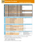
Page 39: ...or more to call up the service monitor mode The service monitor goes on and temperature of the CODE No is firstly displayed 2 Push the temperature setup TEMP buttons to select the CODE No to be monitored For displayed codes refer to the table next page 3 Push SET button to determine the item to be monitored Then monitor the sensor temperature or operation status of indoor unit and the outdoor unit...

Page 40: ... n i s t a e h 2 U D P I r o s s e r p m o C 1 e r u t a r e p m e t k n i s t a e h 1 U D P I n a f r o o d t u O 1 e r u t a r e p m e t k n i s t a e h 2 U D P I n a f r o o d t u O P H 6 1 6 1 0 0 1 r e w o p e s r o h t i n u r o o d t u O 0135 13 5A 1 fan model Compressor 2 and Outdoor fan 1 current I2 2 fan model Compressor 2 and Outdoor fan 2 current I2 10 0 1 s n o i t u l o v e r 1 r o s...

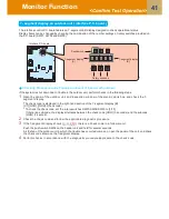
Page 41: ...section of the 7 segment display B U1 OOO OOO Check code To check the check code set the rotary switches SW01 SW02 SW03 to 1 1 1 If there is a sub code the display alternates between the check code OOO 3 seconds and the subcode OOO 1 second 2 Check the check code and follow the applicable diagnostic procedure 3 If the 7 segment display shows there is a check code in a follower unit Push the push s...

Page 42: ... A Oil recovery in cooling C1 Normal C B Refrigerant recovery in heating H1 Normal H 11 Automatic addressing A Ad B During automatic addressing FF Normal 12 Power peak cut A dU B Normal During 50 90 capacity operation _50 _90 While control is based on BUS line input E50 E90 13 B A s u t a t s l o r t n o c l a n o i t p o s y a l p s i D t u p n i d r a o b C P l o r t n o c l a n o i t p O Operat...

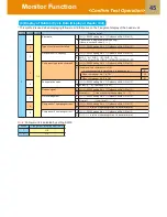
Page 43: ... display 6 Outdoor fan mode A FP B Mode 0 to 63 0 to 63 7 Compressor backup A C b B Displays compressor backup setting status Normal Compressor No 1 backup 1 Compressor No 2 backup 1 8 A B 9 Control valve output data Displays control output status of solenoid valve A B 1 H F F O 2 e v l a v y a w 4 N O e v l a v y a w 4 0 H N O 2 e v l a v y a w 4 F F O e v l a v y a w 4 10 0 0 1 2 SV2 ON SV51 OFF...

Page 44: ... 3 Data 1 E t l o b m y s r e t t e L a t a d r o s n e s 1 E T Data 2 E t l o b m y s r e t t e L a t a d r o s n e s 2 E T Data 1 L t l o b m y s r e t t e L a t a d r o s n e s 1 L T Data 2 L t l o b m y s r e t t e L a t a d r o s n e s 2 L T Data 3 L t l o b m y s r e t t e L a t a d r o s n e s 3 L T Data o t l o b m y s r e t t e L a t a d r o s n e s O T Data SW01 SW02 SW03 1 F l o b m y s...

Page 45: ...2 o N r o s s e r p m o c n e h W 5 Fan operation mode A U SW03 setting No 1 Outdoor unit No U2 to U 3 B At rest F 0 In mode 63 F 6 3 6 Release signal A U SW03 setting No 1 Outdoor unit No U2 to U 3 B Normal r Upon receiving release signal r 1 7 Oil level judgment A U SW03 setting No 1 Outdoor unit No U2 to U 3 B Normal Low level L 8 Compressor 1 operating current A U SW03 setting No 1 Outdoor uni...

Page 46: ...ode Display at each Outdoor Unit B 4 Indoor BUS communication signal receiving status Upon receiving signal 1 Other times B 5 Indoor check code No check code B 6 Indoor HP capacity 0 2 0 5 0 8 1 1 2 1 7 2 2 5 3 3 2 4 5 6 8 1 0 1 6 2 0 8 Indoor PMV opening data Displayed in decimal format 9 1 4 1 16 Indoor TA TRA opening data Displayed in decimal format 11 1 Indoor TSA opening data Displayed in dec...

Page 47: ... with the expected system capacity Check No of outdoor units Set the rotary switches SW01 SW02 SW03 on the interface P C board of the header unit to 1 3 3 Then No of outdoor units connected to the system is displayed on 7 segment display A Check that this display surely matches with the expected No of outdoor units Check No of indoor units No of units with cooling thermostat ON Set the rotary swit...

Page 48: ...ture of the indoor heat exchanger TC indicates TCJ sensor temperature when cooling and TC2 sensor temperature when heating respectively 2 Criteria for operating pressure Criteria after 15 minutes or more has passed since operating started Indoor temperature C Outdoor temperature C Operating mode Cooling Heating 15 25 5 10 2 5 3 3 0 5 0 7 18 32 25 35 2 0 3 7 0 5 0 9 Pressure High pressure MPa Low p...

Page 49: ...f check results 2 Push the push switch SW05 on the interface P C board of the header unit for 2 seconds or more The indoor address in which error is being detected is displayed on 7 segment display B If there are multiple indoor address in which check code is being detected they are successively exchanged and displayed When SW05 is turned on again the display returns to display of No of units Afte...

Page 50: ... 1 1 Section A F Section B F 4 Batch start Starts all the connected indoor units collectively Note The contents follow to the setup of remote controller Setup Set SW01 SW02 SW03 to 2 7 1 and push SW04 for 2 seconds or more Release Return SW01 SW02 SW03 to 1 Section A C H Section B 11 Section A Displays the corresponding indoor address Section B Displays 11 for 5 seconds from operation ON 5 Individ...

Page 51: ...e sure to turn on power at the indoor side before power ON of outdoor unit Set SW01 SW02 SW03 on the interface P C board of the header unit to 2 5 1 C is displayed on 7 segment display A Test run is displayed on the remote controller of the indoor unit to be operated Check that C is displayed on 7 segment display B on the interface P C board of the header unit Push SW04 on the same board for 2 sec...

Page 52: ...ush SW04 on the same board for 2 seconds or more Test run is displayed on the remote controller of the indoor unit to be operated Check that H is displayed on 7 segment display B on the interface P C board of the header unit Set SW01 SW02 SW03 on the interface P C board of the header unit to 2 6 1 H is displayed on 7 segment display A Be sure to turn on power at the indoor side before power ON of ...

Page 53: ...e push switch SW4 for 2 seconds or more on the P C board Test run is displayed on the remote controller of the indoor unit to be operated Check that 7 segment display B on the interface P C board of the header unit changed to C Match SW01 SW02 SW03 on the interface P C board of the header unit to 2 5 1 7 segment display A changes to F Be sure to turn on power of the indoor unit and then turn on po...

Page 54: ...ot operated In this case operation ready or operation mode controlled is displayed on the remote controller If the discharge temperature does not change though COOL or HEAT has been set up from the remote controller misconnection is considered Push SW04 on the same board for 2 seconds or more The indoor unit to be started operates Push the push switch SW05 on the interface P C board of the header ...

Page 55: ...rvice monitor mode by pushing CL TEST buttons simultaneously for 4 seconds or more 2 Using TEMP buttons set CODE No to 3 The display in Section A in the following figure is counted with interval of 5 seconds as When the count arrives the check code is cleared However counting from is repeated on the display 4 When TEST button is pushed the status returns to the normal status Check code clearing in...

Page 56: ...oor units are once cleared and check code detection is performed again Method 1 Be sure to reset power of both the outdoor and the indoor units 2 Turn on the power of the indoor unit prior to the power of the outdoor unit If the power is turned on in reverse order a check code No of header unit check code is output NOTE After power reset it requires usually 3 minutes to power on due to the initial...

Page 57: ...play A B A 1 FF Be sure to turn on the power of the indoor unit prior to the power of the outdoor unit Set the display select switches on the interface P C board of the header unit as follows Set SW01 SW02 SW03 to 2 4 1 Push the push switch SW04 on the same board for 2 seconds or more Checking display of the connected remote controller flashes Push the push switch SW05 on the interface P C board o...

Page 58: ...ed in the outdoor unit for 2 minutes PMV1 Open fully On the interface board of the outdoor unit set the DIP switch SW12 bit1 to OFF SW12 bit2 to OFF and short circuit CN30 PMV1 Close fully On the interface board of the outdoor unit set the DIP switch SW12 bit1 to OFF SW12 bit2 to OFF and short circuit CN31 Heat Recovery type Not use Heat Recovery type Not use On the interface P C board of the outd...

Page 59: ...pt with the same number for 5 seconds or more NOTE 2 The mark O in the table indicates that the corresponding solenoid valve is forcedly turned on NOTE 3 The mark in the table indicates that ON OFF of the solenoid valve is controlled based upon the specifi cations of the air conditioner NOTE 4 The mark in the table indicates that the corresponding solenoid valve is forcedly turned off with this op...

Page 60: ...peration 4 After that by changing the setup number of the switches SW02 and SW03 7 segment display B and the fan mode are changed Mode output pattern of the fan is as follows Clear This function is cleared by one of the following operations 1 When SW01 setting number was changed to other number 2 Push switch SW05 was push for 2 seconds or more SW02 SW03 7 segment display B Fan mode 1 4 63 63 2 62 ...

Page 61: ...onds or more 3 E 1 is displayed on 7 segment display A 4 The fan of the outdoor unit in which check code occurred starts operation within approx 10 seconds after was displayed In case to operate the fans in all the normal outdoor units 1 Check that the switches SW01 SW02 SW03 on the interface P C board in the header unit are set to 1 1 1 2 Push the push switches SW04 and SW05 at the same time for ...

Page 62: ...n the interface P C board for 1 second or more The mode changes to the TO sensor value fix manual mode 3 As shown in the following table TO sensor value can be fixed by setting the rotary switch SW02 on the interface P C board Clear Return SW01 SW02 SW03 on the interface P C board in the outdoor unit to 1 1 1 NOTE If operated with TO sensor fixed by this function the system control operation of th...

Page 63: ...u f e s o l c n e p o d e c r o f e v l a v d i o n e l o S r H 2 1 16 4 7 n o i t c n u f n o i t a r e p o d e c r o f n a F d F 2 15 n o i t c n u f t n e m t s u j d a l a u n a m r o s n e s e r u t a r e p m e t e d i s t u O o t 2 n o i t c n u f n o i t a r e p o t s e t g n i t a e H H 6 n o i t c n u f F F O N O p o t s t r a t s e v i t c e l l o c r o o d n I H C 7 n o i t c n u f n w ...

Page 64: ...ted leakage determination is not possible c Due to the outside temperature the initial value may not be recorded or it may be impossible to determine the leakage SW01 SW02 SW03 Display detail 2 13 14 Refrigerant leakage detection A B L d SW01 SW02 SW03 Display detail 2 14 14 Colling initial value A C i Incomplete 0 Completed 1 B 2 15 14 Heating initial value A H i Incomplete 0 Completed 1 Clear th...

Page 65: ...etected OFF Entire system stops ON System operation continues Room which trouble occurred only stops OFF SW16 DIP SW 4 bit bit 1 Option function Output exchange of external output P C boa According to the following setting contents OFF SW14 DIP SW 4 bit bit 1 Line address setup OFF bit 1 bit 2 OFF OFF Compressor operation output ON OFF bit 2 OFF bit 2 OFF bit 3 OFF bit 4 OFF SW13 DIP SW 4 bit bit ...

Page 66: ...uccessive MAKE or Pulse signal 2 core wire Successive MAKE signal O Approx 75 Normal The mode is changed a mode which selected the operation mode of the indoor unit at not selected side Approx 60 J04 O Upper limit setup of demand capacity command in corresponding indoor during saving operation in indoor 4 When you replace the board with a service board be sure to cut the jumper wire matching with ...

Page 67: ...it Oil level low detection and protection H07 Oil level low Reducer I Corresponding unit Oil level detection circuit trouble Oil level low detection and protection H16 05 H07 Oil circuit trouble Oil level low Oil level low w o l l e v e l l i O 7 0 H n o i t c e t o r p d n a n o i t c e t e d w o l l e v e l l i O t i n u g n i d n o p s e r r o C J r o t u b i r t s i d n r u t e r l i O Oil cir...

Page 68: ...r Low pressure sensor Oil separator Fusible plug Liquid Tank Accumulator High pressure switch High pressure switch Check valve Check valve Compressor 1 Inverter Oil Header Liquid side Service valve Gas side Service valve Balance pipe Service valve Sub cool heat exchanger SV SV52 Reducer FP Compressor 2 Inverter SV Solenoid valve Capillary tube Check valve Check joint Strainer Temperature sensor Sy...

Page 69: ...essor there is a leak from the oil equalization pipe check valve F Replace the part Leakage of SV3A valve G 5 With pressure applied to the check joint of discharge pipe with nitrogen manually open the SV3B valve If gas escapes from the suction pipe section of the disconnected compressor there is a leak from the SV3A valve Replace the part Leakage of SV3B valve H 6 Then manually open the SV3A valve...

Page 70: ...n and protection H07 Oil level low Reducer I Corresponding unit Oil level detection circuit trouble Oil level low detection and protection H16 05 H07 Oil circuit trouble Oil level low Oil level low w o l l e v e l l i O 7 0 H n o i t c e t o r p d n a n o i t c e t e d w o l l e v e l l i O t i n u g n i d n o p s e r r o C K r o t u b i r t s i d n r u t e r l i O Oil circuit trouble 4 0 6 1 H Oi...

Page 71: ...er Left side Sub heat exchanger PMV1 PMV3 4 way valve High pressure sensor Low pressure sensor Oil separator Accumulator Liquid Tank Liquid side Service valve Gas side Service valve Balance pipe Service valve Oil Header High pressure switch High pressure switch Reducer Fusible plug FP Sub cool heat exchange Compressor 1 Inverter Compressor 2 Inverter SV Solenoid valve Capillary tube Check valve Ch...

Page 72: ...ected compressor there is a leak from the oil equalization pipe check valve F Replace the part Leakage of SV3A valve G 5 With pressure applied to the check joint of discharge pipe with nitrogen manually open the SV3B valve If gas escapes from the suction pipe section of the disconnected compressor there is a leak from the SV3A valve Replace the part Leakage of SV3B valve H 6 Then manually open the...

Page 73: ...l level low Reducer I Corresponding unit Oil level detection circuit trouble Oil level low detection and protection H16 05 H07 Oil circuit trouble Oil level low Oil level low w o l l e v e l l i O 7 0 H n o i t c e t o r p d n a n o i t c e t e d w o l l e v e l l i O t i n u g n i d n o p s e r r o C K r o t u b i r t s i d n r u t e r l i O Oil circuit trouble 4 0 6 1 H Oil level detection circu...

Page 74: ...t side Sub heat exchanger Left side Sub heat exchanger PMV1 PMV3 4 way valve High pressure sensor Low pressure sensor Oil separator Accumulator Liquid Tank Liquid side Service valve Gas side Service valve Balance pipe Service valve Oil Header High pressure switch High pressure switch Reducer Fusible plug FP Sub cool heat exchange Compressor 1 Inverter Compressor 2 Inverter SV Solenoid valve Capill...

Page 75: ...is a leak from the oil equalization pipe check valve F Replace the part Leakage of SV3A valve G 5 With pressure applied to the check joint of discharge pipe with nitrogen manually open the SV3B valve If gas escapes from the suction pipe section of the disconnected compressor there is a leak from the SV3A valve Replace the part Leakage of SV3B valve H 6 Then manually open the SV3A valve If gas esca...

Page 76: ...ction H07 Oil level low Reducer I Corresponding unit Oil level detection circuit trouble Oil level low detection and prote H16 05 H07 Oil circuit trouble Oil level low Oil level low w o l l e v e l l i O 7 0 H n o i t c e t o r p d n a n o i t c e t e d w o l l e v e l l i O t i n u g n i d n o p s e r r o C K r o t u b i r t s i d n r u t e r l i O Oil circuit trouble 4 0 6 1 H Oil level detectio...

Page 77: ...b heat exchanger Left side Sub heat exchanger PMV1 PMV3 4 way valve High pressure sensor Low pressure sensor Oil separator Accumulator Liquid Tank Oil Header High pressure switch High pressure switch Sub cool heat exchanger Fusible plug FP Liquid side Service valve Gas side Service valve Balance pipe Service valve SV Solenoid valve Capillary tube Check valve Check joint Strainer Temperature sensor...

Page 78: ...ed compressor there is a leak from the oil equalization pipe check valve F Replace the part Leakage of SV3A valve G 5 With pressure applied to the check joint of discharge pipe with nitrogen manually open the SV3B valve If gas escapes from the suction pipe section of the disconnected compressor there is a leak from the SV3A valve Replace the part Leakage of SV3B valve H 6 Then manually open the SV...

Page 79: ... short circuit A fault occurs in a refrigerating cycle part fan or related part or electrical part A fault occurs in a temperature sensor or pressure sensor Failure Failure Prohibited Example Backed up compressor Backed up compressor Prohibited Example Backed up outdoor unit Backed up outdoor unit Prohibited Example Backed up outdoor unit Backed up compressor Prohibited Example Backed up outdoor u...

Page 80: ...the outdoor units connected to the system 2 Set the DIP switches of SW06 provided on the interface P C board of the outdoor unit with the faulty compressor as shown in the table below SW06 Bit 1 Bit 2 Bit 3 Bit 4 When compressor No 1 front left is faulty ON OFF OFF OFF When compressor No 2 front right is faulty OFF ON OFF OFF Factory default setting OFF OFF OFF OFF 1 2 3 4 1 2 3 4 1 2 3 4 1 2 3 4 ...

Page 81: ...iring between Como IPDU and Fan IPDU as shown in the below CN21 CN23 CN21 CN23 CN21 CN23 CN21 CN23 Change the connection of wiring which is connected to the CN21 23 of Comp IPDU2 Change to CN21 of Comp IPDU1 from CN21 of Comp IPDU2 Change to CN23 of Comp IPDU2 from CN23 of Comp IPDU2 Change the connection of wiring which is connected to the CN21 23 of Comp IPDU2 Change to CN21 of Comp IPDU1 from C...

Page 82: ...iring which is connected to the CN21 23 of Comp IPDU1 Change to CN22 of Comp IPDU2 from CN21 of Comp IPDU1 Change to CN23 of Comp IPDU2 from CN23 of Comp IPDU1 Tighten two wirings together with screw terminal Change the connection of wiring which is connected to the CN21 23 of Comp IPDU2 Change to CN22 of Comp IPDU1 from CN21 of Comp IPDU2 Change to CN23 of Comp IPDU1 from CN23 of Comp IPDU2 Tight...

Page 83: ...d pipe service valve 4 In case of fault in compressor electrical part I F P C board or IPDU P C board From this point on keep the power supply to the failed unit off In case of fault in refrigerating circuit or related part pressure sensor temperature sensor refrigerating cycle part or fan system part Disconnect the connector CN03 for outdoor outdoor communication BUS2 provided on the interface P ...

Page 84: ...Perform settings needed to gain permission for backup operation from the header unit error clearance 1 Set SW01 02 03 on the interface P C board to 1 1 1 and confirm that U1 E26 dropping out of an outdoor unit is displayed on the 7 segment display 2 Set SW01 02 03 on the interface P C board to 2 16 1 Upon confirming that Er is displayed on the 7 segment display press SW04 and hold for 5 seconds or...

Page 85: ...n system part Disconnect the connector CN03 for outdoor outdoor communication BUS2 provided on the interface P C board Selection of new header unit 5 Select a new header unit from the follower units on the basis of the following criteria If only one follower unit is connected select it as the header unit If two follower units are connected select the follower unit that is nearest to the failed hea...

Page 86: ...art Turn on the power supply to protect the compressor by turning on the case heater When the power supply to the unit is turned on E19 error in the number of outdoor header units will be displayed on the 7 segment display However this will not cause any problems This is the end of header outdoor unit backup operation setting Check the operation 1 2 3 4 1 2 3 4 1 2 3 4 1 2 3 4 1 2 3 4 1 2 3 4 1 2 ...

Page 87: ...s function is not available In that case follow the procedure specified in the Outdoor Unit Backup Operation Setting section Work procedure 1 Turn off the power supply to all the units connected to the system Setup of failed outdoor unit Regardless of whether the failed outdoor unit is the header unit or a follower unit there is no difference in the setup procedure 2 Turn on Bits 1 and 2 of SW06 p...

Page 88: ... of the functions of the auto address setup and test operation at its own responsibility and also be sure to confirm notices in the Operating Manual before performing the test operation If you want to disable the functions of the auto address setup and the test operation perform the following operations Switch setting of some functions prohibition How to set the NFC operation all time prohibition ...

Page 89: ...1 1 U 1 Return the switch Step Rotaly switch NFC I F board communication 1 2 16 14 Do it again if the 7 segment display is different from the above The functions other than the auto address setup and test operation of this Application can work normally even if the functions of the auto address setup and the test operation are disabled Confirmation for the generation of the trouble of the NFC When ...

Page 90: ...er and follower unit Periodic communication between indoor header and follower units cannot be maintained Indoor heat exchanger temperature sensor TCJ error Heat exchanger temperature sensor TCJ has been open short circuited Indoor heat exchanger temperature sensor TC2 error Heat exchanger temperature sensor TC2 has been open short circuited Indoor heat exchanger temperature sensor TC1 error Heat ...

Page 91: ...er Both remote controllers have been set as master remote controller in two remote controller control alarm and shutdown for header unit and continued operation for follower unit Check code Display of receiving unit Typical problem site Description of problem TCC LINK central control Outdoor 7 segment display Indicator light block Sub code Flash C05 No indication when main remote controller also i...

Page 92: ... unit from other refrigerant line is detected while indoor automatic address setting is in progress E23 E23 Outdoor outdoor communication transmission error Signal cannot be transmitted to other outdoor units E25 E25 Duplicated follower outdoor address There is duplication in outdoor addresses set manually E26 Address of outdoor unit from which signal is not received normally E26 E28 of outdoor un...

Page 93: ...l circuit error 02 TK2 oil circuit error 04 TK4 oil circuit error 05 TK5 oil circuit error H16 Oil level detection circuit error No temperature change is detected by temperature sensor for oil level detection TK1 despite compressor having been started Duplicated outdoor refrigerant line address Identical refrigerant line address has been assigned to outdoor units belonging to different refrigerant...

Page 94: ...door liquid backflow detection error State of refrigerant cycle circuit indicates liquid backflow operation P15 P13 P10 P10 P07 P05 P03 P03 L30 L29 L29 SIM SIM ALT ALT ALT ALT ALT ALT Gas leak detection Indoor unit overflow ALT ALT ALT Error in number of IPDUs L30 P17 P19 P20 01 TS condition 02 TD condition Outdoor suction temperature sensor TS1 detects sustained and repeated high temperatures tha...

Page 95: ... Compressor 2 H02 H01 F13 Compressor error lockup Compressor lockup is detected H03 01 Compressor 1 02 Compressor 2 H03 P04 P07 P22 P26 P29 Current detection circuit error Compressor breakdown Abnormal current is detected while inverter compressor is turned off P04 01 Compressor 1 02 Compressor 2 Activation of high pressure SW High pressure SW is activated P07 01 Compressor 1 02 Compressor 2 Heat ...

Page 96: ...Quick Reference ...
Reviews: