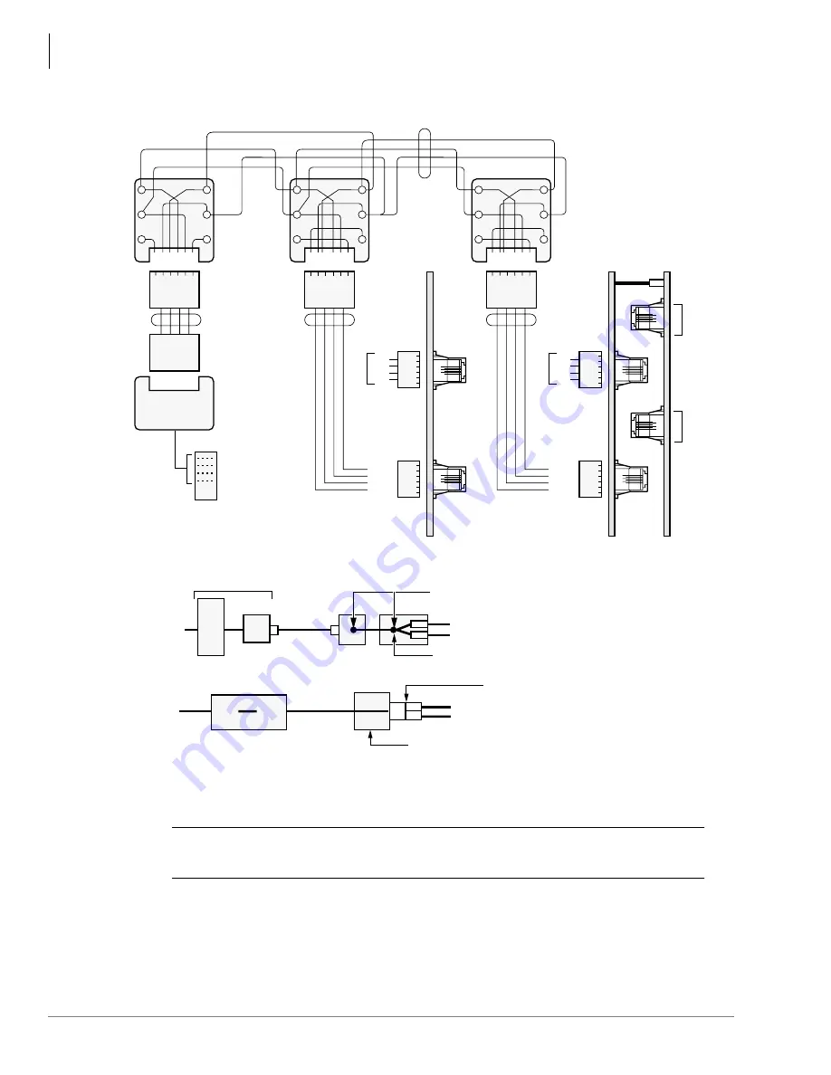
Universal Slot PCB Wiring
CO Line Wiring Diagrams
10-30
Strata DK I&M 6/00
GN
6 5 4 3 2 1
Y
BL
R
BK
W
2 3 4 5
Modular
Cords
R1
R2
T1
T2
Dealer Supplied
Modular Block,
625-Type or
Equivalent
(See Notes)
R2
R1
T1
T2
5
4
3
2
CKT 7&8
1-6
1-6
CKT 3&4
CKT 5&6
RCIU
RCIS
CKT 1&2
1
2
3
4
5
6
Same
Same
Same
R4
R3
T3
T4
5
4
3
2
1
2
3
4
5
6
GN
6 5 4 3 2 1
Y
BL
R
BK
W
2 3 4 5
2 3 4 5
4-Wire
Modular
Cord
4-Wire
Modular
Cord
Telco
RJ14C
Modular Jack
T1
T2
Dealer Supplied
Modular Block,
625-Type or
Equivalent
(See Notes)
Bridging Jumper Wires
R1
R1
R2
R2
GN
6 5 4 3 2 1
Y
BL
R
BK
W
T1
T2
Dealer Supplied
Modular Block,
625-Type or
Equivalent
(See Notes)
R2
R1
T1
T2
T1
R1
T2
R2
LINE X
LINE Y
Telco
RJ21X
5
4
3
2
Network Jack: RJ14C/RJ21X
FIC: 02LS2 (Loop Start) OR 02GS2 (Ground Start)
6-1
6-1
6-1
6-1
CKT 3&4
RGLU/RCOU/RCOS/PCOU/TCOU
Pin-out
Pin-out
CKT 1&2
1
2
3
4
5
6
Same
R4
R3
T3
T4
5
4
3
2
1
2
3
4
5
6
Network
RJ21X
Network
RJ14C
RJ14C
Telco Jacks
Telco RJ21X
4-Wire
Modular
Cord
Installer Cross Connect Customer
Supplied Modular Jacks
Duplex Modular Jack (AA-104A-4 or Equivalent)
RCOU 4-Wire Modular Cord
1
4-Wire Single Modular Jack (RJ14C) from Telco
RCIU/RCIS 4-Wire Modular Cord
2
RCOU 4-Wire Modular Cord
1
4-Wire Connector (267A2 Or Equivalent)
RCIU/RCIS 4-Wire Modular Cord
2
1608
1. 4-wire modular jacks such as graybar part number AA-104A-4 could be used in place of the two modular jacks; or,
a T-connector such as graybar part number 267A2 Adaptor could be used as shown below:
2. Assign RCIU1/RCIU2/RCIS circuits to the appropriate CO line using Program *50.
CAUTION!
RCIU1 cannot be used in DK40i. Install RCIU2 in slot 17 only of the
DK40i Expansion Unit; it must never be installed in slot 18.
Figure 10-28 RCIU1/RCIS or RCIU2/RCIS MDF Wiring Diagram
Summary of Contents for Strata AirLink DK40i
Page 22: ...Introduction Related Documents Media xx Strata DK I M 6 00 ...
Page 48: ...DK14 Installation DK14 Wiring Diagrams 1 26 Strata DK I M 6 00 ...
Page 220: ...DK424 Installation Remote Cabinet Installation Instructions 5 68 Strata DK I M 6 00 ...
Page 262: ...DK424i Configuration Primary Reserve Power Cabinet Hardware 6 42 Strata DK I M 6 00 ...
Page 450: ...Universal Slot PCB Wiring Option Interface PCB Wiring Diagrams 10 42 Strata DK I M 6 00 ...
Page 592: ...Peripheral Installation Enhanced 911 Service E911 12 84 Strata DK I M 6 00 ...
Page 616: ...ACD Installation Spectrum Electronic Wall Boards 13 24 Strata DK I M 6 00 ...
Page 634: ...Fault Finding Fault Isolation Flowcharts 14 18 Strata DK I M 6 00 ...
Page 704: ...ISDN Interfaces ISDN Disconnect Cause Code 16 54 Strata DK I M 6 00 ...


