Station Apparatus
Electronic Telephone Upgrades
11-26
Strata DK I&M 6/00
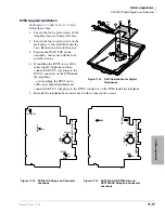
For the V.4 HHEU1 or the HHEU2: if only the headset is connected to the HHEU, cut the
speaker OCA strap.
Note
Do not cut the speaker OCA strap if connecting an HESB to the HHEU for the loud
ringing bell–even if a headset is also installed on the HHEU.
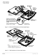
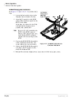
6. Position the HHEU subassembly on the standoffs inside the base, and secure with the two
screws provided.
7. Connect the HHEU subassembly wire plug to the P1 connector on the electronic telephone
PCB.
8. Cut the HHEU strap on the telephone PCB.
Note
The HHEU strap must be replaced if the HHEU PCB is removed from the telephone.
9. Reinstall the telephone base, and secure it with its four captive screws.
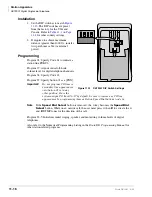
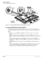
Adjust (HESB) Loud Ringing Bell Volume
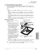
1. Call the telephone connected to the HESB.
2. Adjust the volume control on both the back of the HESB and the ring volume control on the
telephone.
Carbon Headset/Handset Straps
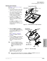
If a carbon-type handset or headset is connected to the handset jack on the side of the 6500-series
electronic telephone, two straps inside the telephone must be cut.
➤
To cut the straps
Note
It is not necessary to cut these straps if the headset is connected to the HHEU.
See
and follow these steps:
1. Loosen the four captive screws on the telephone base and remove the base.
2. Locate the carbon straps, W201 and W202 and cut them.
3. Reinstall the telephone base, and secure it with its four captive screws.
Beep Strap
A “beep” sounds whenever a dial pad button or feature button is pressed on an electronic
telephone.
➤
To eliminate the beep
See
and follow these steps:
1. Remove the four captive screws on the telephone base to the telephone and remove the base.
2. Locate and cut the beep strap on the telephone PCB.
3. Reinstall the electronic telephone base and secure in place using the four captive screws.
Summary of Contents for Strata AirLink DK40i
Page 22: ...Introduction Related Documents Media xx Strata DK I M 6 00 ...
Page 48: ...DK14 Installation DK14 Wiring Diagrams 1 26 Strata DK I M 6 00 ...
Page 220: ...DK424 Installation Remote Cabinet Installation Instructions 5 68 Strata DK I M 6 00 ...
Page 262: ...DK424i Configuration Primary Reserve Power Cabinet Hardware 6 42 Strata DK I M 6 00 ...
Page 450: ...Universal Slot PCB Wiring Option Interface PCB Wiring Diagrams 10 42 Strata DK I M 6 00 ...
Page 592: ...Peripheral Installation Enhanced 911 Service E911 12 84 Strata DK I M 6 00 ...
Page 616: ...ACD Installation Spectrum Electronic Wall Boards 13 24 Strata DK I M 6 00 ...
Page 634: ...Fault Finding Fault Isolation Flowcharts 14 18 Strata DK I M 6 00 ...
Page 704: ...ISDN Interfaces ISDN Disconnect Cause Code 16 54 Strata DK I M 6 00 ...

