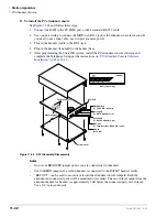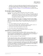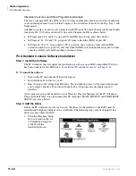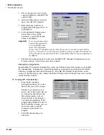
Station Apparatus
Cordless Digital Telephones
11-36
Strata DK I&M 6/00
Cordless Telephone Connectors
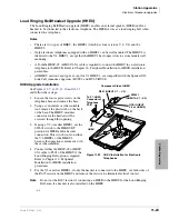
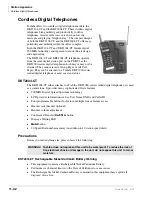
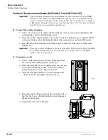
2. Plug the AC adapter into a standard 120VAC
wall outlet.
3. Route the power cord where it is not a trip
hazard, and where it will not become chafed and
create a fire or electrical hazard.
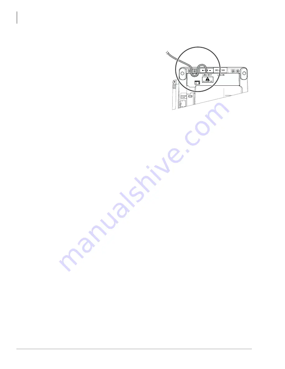
4. Wrap the power cord around the notch on the
bottom of the base unit (see
5. Check to see that the power LED is on,
indicating the telephone has power.
6. Before using your cordless digital telephone, be
sure to raise the antenna to the vertical position.
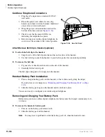
Attach/Remove Belt Clip to Handset (optional)
➤
To attach the belt clip to the handset
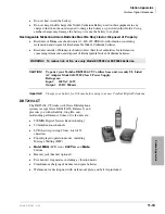
1. Snap the tabs of the belt clip into the notches on the sides of the handset.
2. Use the belt clip to attach the handset to your belt or pocket for convenient portability.
➤
To remove the belt clip
1. Pry one tab at a time from the notch on the side of the handset.
2. Carefully lift the belt clip off.
The belt clip is designed to fit snugly onto the handset.
Handset Battery Pack Installation
1. Place a charged battery pack onto the handset so that it slides easily along the ridges.
If your battery is not charged, see
“Removing and Charging Your Battery Pack” on Page
2. Slide the battery pack up onto the handset until it clicks into place.
You are now ready to configure your cordless digital telephone.
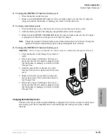
Removing and Charging Your Battery Pack
Before using your new cordless digital telephone, the battery must be charged continuously for 6
to 8 hours.
➤
To remove the handset’s battery pack
1. Press in on the battery pack release latch.
2. Slide the battery pack off the handset.
Note
You may have to pull hard to slide the battery pack off, when the handset is new.
1175
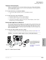
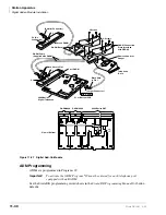
Figure 11-26
Line Out Cord
Summary of Contents for Strata AirLink DK40i
Page 22: ...Introduction Related Documents Media xx Strata DK I M 6 00 ...
Page 48: ...DK14 Installation DK14 Wiring Diagrams 1 26 Strata DK I M 6 00 ...
Page 220: ...DK424 Installation Remote Cabinet Installation Instructions 5 68 Strata DK I M 6 00 ...
Page 262: ...DK424i Configuration Primary Reserve Power Cabinet Hardware 6 42 Strata DK I M 6 00 ...
Page 450: ...Universal Slot PCB Wiring Option Interface PCB Wiring Diagrams 10 42 Strata DK I M 6 00 ...
Page 592: ...Peripheral Installation Enhanced 911 Service E911 12 84 Strata DK I M 6 00 ...
Page 616: ...ACD Installation Spectrum Electronic Wall Boards 13 24 Strata DK I M 6 00 ...
Page 634: ...Fault Finding Fault Isolation Flowcharts 14 18 Strata DK I M 6 00 ...
Page 704: ...ISDN Interfaces ISDN Disconnect Cause Code 16 54 Strata DK I M 6 00 ...

